 FB
FB
I've noticed that many of you are wanting to share Microsoft Excel files. You can upload them into your messages just like other files. This should simplify the process of sharing the spreadsheets rather than having to email them to one another.
Highest Reputation Content
#5255 Uploading Ms Excel Spreadsheets
 Posted by
on 18 March 2006 - 05:08 PM
Posted by
on 18 March 2006 - 05:08 PM
#96123 Revision Calculos Tanque Api 650, Edicion 12, Marzo 2013
 Posted by
on 17 June 2015 - 05:40 AM
Posted by
on 17 June 2015 - 05:40 AM
Señor TALVI y demás miembros del Blog adjunto memorias de cálculos en Excel para su revisión técnica, ingeniería y conceptos que ustedes consideren que se deben tener en cuenta en este diseño.
La idea es que revisen estas memorias y la complementen con sus conocimientos y experiencia.
En este proyecto que estoy desarrollando se van a construir doce tanques así: Cuatro (4) de acero al carbono en SA-36, uno (1) en Acero inoxidable tipo 316 y seis (6) en PRFV o fibra de vidrio, con capacidad cada uno de 42.5 ton. para almacenar productos para químicos para tratamientos de aguas.
En las memorias están los datos del este producto del tanque N° 1 de acero al carbono. Mi objetivo es que este software en Excel le sirva a todos los miembros de la comunidad.
a la espera de su valioso aporte.
Saludos
Attached Files
-
 MEMORIA -TANQUE N 1° LA2326C.xls 3.61MB
605 downloads
MEMORIA -TANQUE N 1° LA2326C.xls 3.61MB
605 downloads
#82070 How About An "in Development" Section In Downloads?
 Posted by
on 19 January 2014 - 01:14 PM
Posted by
on 19 January 2014 - 01:14 PM
Sharing your work (calculations / excel workbooks) can be done only with an open heart and a mind free of suspicion.
It is outright hilarious when people claim that the calculation they have created in the form of an excel workbook is their original work. Most of the engineering calculations that we do today have their roots in the physical laws, principles, formuals, and equations developed by pioneers and researchers in the field of engineering and science long before many of us had even understood what engineering calculations are.
People who are developing calculations / excel workbooks are only organizing and representing the work in a proper sequence and in a manner which is easy to understand and present. Yes, it takes time and effort to do this, and those who have undertaken this task need to be appreciated.
I have never endorsed spoon feeding to young engineers because it allows them to think that there is an easy way out for everything. Many of the blog entries in my blog are related to engineering calculations where I have exhorted the engineers to prepare excel workbooks based on the calculation steps mentioned. For each and everyone of these blog entries related to chemical engineering calculations, I have developed an excel calculation workbook, which I have not shared for the very same aforementioned reason.
However, I do want to make a public pledge today. When my eyesight starts betraying me and my hands are no longer able to type on the keyboard of a computer, I would like to donate my entire set of chemical engineering calculation workbooks to "Cheresources" for Chris Haslego to use in a manner he deems fit for the good of the chemical engineering community.
Regards,
Ankur
#122007 I Need 2020 Cepci
 Posted by
on 02 November 2020 - 07:17 AM
Posted by
on 02 November 2020 - 07:17 AM
Hi,
The last one on hands is from august 2020 .
Sorry I don't have anymore a subscription to CHE .
Good luck
Breizh
#118338 Pressure Relief Valve Accumulation Pressure
 Posted by
on 08 May 2019 - 01:32 PM
Posted by
on 08 May 2019 - 01:32 PM
surendra:
I highly recommend that you take Latexman's concise and terse response as an important one. His comment is meant to be taken in jest. He is precisely correct in his statement and I only take this time to add to his valuable advice.
It is very important that you learn and apply what his statement and recommendation implies. I am certain that he is assuming that you have invested as much time and effort in the application of safety relief devices as he has, and for that reason I am attaching a document I prepared some time back in replying to a student that had problems with the same topic. You rightfully show concern for the accumulated pressure realized in a pressure relief valve and you correctly give importance to the MAWP. However, I believe you lack the knowledge of how the MAWP is calculated and under what correct basic data and assumed conditions. You also seem to not be aware of the usual and normal way a pressure vessel is subjected to a required hydrostatic test. A hydro is far in excess of the MAWP. So, can this be???
Experienced and knowledgeable engineers, such as Latexman, don't have disdain for the value of a pressure vessel's MAWP. On the contrary. They are aware and mindful of the precise conditions under which it is calculated, its specific intentions, and how it applies to engineering design and operations. Please read the attached and you will further appreciate what he has stated.
 MAWP as Applied to PSVs.docx 107.56KB
146 downloads
MAWP as Applied to PSVs.docx 107.56KB
146 downloads
#93253 Condensate Pot Equalisation Line
Posted by
on 27 February 2015 - 01:31 PM
I’ve lost count of how many equalization line “problems” I’ve resolved in the field in the past 55 years. It must be around 10 to 20. In almost every one of these so-called “problems” the cause has always turned out to be a cheap, quick, and last-minute process engineering or piping designer “solution” to a basic process design screw-up. I’ve resolved the problem as shown in the attached revised sketch.
The typical situation is where a process engineer turns over the process design to a mechanical engineering team composed of usually mechanical engineers and piping designers (who are not engineers). The basic process design package should contain all the process information critical to mechanically designing and fabricating a reliable and controllable piece of equipment. This involves the correct sizing of attached piping, nozzles, vents, safety valves, drains, and EQUALIZATION lines. Their locations are also required to be specified. All this information and its communication should be carefully organized and scheduled according to project needs. What usually happens in the case where a heat exchanger - especially a steam-heated one - is concerned is that the process engineer turns over his deliverables to a heat transfer engineer who produces the heat exchanger design for fabrication. The need for an equalization line is left to a piping designer’s decision or criteria. In this process, there is inevitably an oversight in failing to point out the need to control the production, flow and control of steam condensate produced in the exchanger. The fabrication drawings for the exchanger go out approved without any thought as to how the condensate flow will be gravity drain-controlled and this become apparent when the exchanger is delivered. The solution to ensuring that the condensate flow is allowed to drain under gravity to the respective condensate drum: quickly connect the condensate drum to the steam supply line. This is quick, cheap, and presumably vents the condensate to a pressure “equal” to that where it originates, and it eliminates the need to do a re-work on the exchanger bonnet (possibly requiring an ASME stamp, expensive and time consuming). WRONG! The steam supply pressure is NOT equal to the condensate origin pressure - it is higher by the exchanger’s pressure drop. The term “equalization” means exactly that: the pressure in the drum should equal the pressure at the condensate’s origin. This allows for free, un-interrupted gravity flow. The true and correct origin pressure unfortunately exists in the exchanger’s bonnet last tube pass. This fact should have been specified by the process and exchanger engineers prior to exchanger fabrication. An inexperienced or flawed engineering design has caused a more expensive, correct modification. In today’s engineering world, this type of flawed, embarrassing design is becoming more repetitive than engineering houses would like to admit.
I have preached this reality countless times on our forums and have probably become an un-welcomed bore. I promise this will be the last time. Samroo’s recommendation is the correct answer.
Attached Files
-
Condensate Pot Equalization Line.xlsx 14.09KB
449 downloads
#88971 Chemical Engineering Plant Cost Index (Cepci)
Posted by
on 25 August 2014 - 05:59 PM
Hi,
Year 2013 : 567.3
Final April 2014 : 573.6
Preliminary May 2014 : 574.4
Breizh
#60483 How About An "in Development" Section In Downloads?
Posted by
on 24 May 2012 - 08:56 AM
I have many, many spreadsheets from visitors that have tons of great information in them, but aren't necessarily ready to be opened and used as they exist. Some may need just a little work, some may need a lot of work. Many of them are well referenced in terms of methodology being used.
However, some people may be working on similar projects and may find these helpful. My hope would be to release them in the Downloads section (clearly marked as "Development Items") and to see if the community can work together to turn these into polished projects.
I thought I'd start by collecting initial feedback on the idea. Let me know what you think. These titles would only be visible to registered members of the community.
Thanks,
#129943 Pressure Relief Valve Set Pressure
 Posted by
on 17 August 2023 - 02:04 AM
Posted by
on 17 August 2023 - 02:04 AM
1) Can PSV set pressure be lower than the design pressure of the protected equipment ? Generally in guide books, it is above the design and MAWP of the equipment. However, I was trying to do a more conservative design. For example for a fire case;
Design P of Protected Equipment : XX kg/cm2-g
90% of the Design P : XX*0.9 kg/cm2-g
Set Pressure of the PSV: (XX*0.9) / (1.21) kg/cm2-g (21% for fire scenario)
Relieving pressure of the PSV is (XX*0.9) kg/cm2-g for that case. Can it be done for conservative results ?
2) My second question is: If relieving temperature of the PSV is higher than the pipe spec, could it be a serious problem ? (The distance between the PSV and the equipment is not short.)
Hi,
1) The PSV set pressure shall be equal to or lower than the MAWP of the relevant equipment; hence lower set pressure is more conservative but care should be taken not to be so close to the maximum operating pressure.
2) In general, the relieving temperature shouldn't be higher than the pipe spec; but the relieving temperature of the fire case is exceptional and in such case the relieving temperature could be higher than the pipe spec...
#124688 Water In Diesel Due To Condensed Moisture From Air Ingress From Vents
 Posted by
on 31 October 2021 - 07:58 AM
Posted by
on 31 October 2021 - 07:58 AM
I am not an expert on storage matters but I will give you my opinion anyway:
Recently we have found that there are a lot of free water in our diesel system............A root cause analysis has been done by the operation team members and the air ingress through the vents into the system and moisture condensation was considered as a main suspect. (An estimate amount of 30 to 50 liter per day of moisture condensation). During the previous 2 weeks we have drained about 20 m3 free water from the system.
20 m3 in 2 weeks would be 1400 liter per day on average, not 50 liter per day.
Lots of water condensation from ambient air in diesel tanks seems highly unlikely to me.
You indicate that the problem is recent, so the ambient air is unlikely to be the problem. Climate change does not occur that fast.
You should however check for any rain water leakage.
For water to condense from air it requires contact with a surface that is colder than its dewpoint.
According to the drawing each diesel tank has an electric heater on TC. What is the setpoint of this TC ? What is the dewpoint of the ambient air?
As the problem is recent: what changed just before the problem started? That's what you should focus on.
If nothing changed inside your unit then something must have changed outside your control.
The most likely suspect is then the supplier of the diesel, or the refinery where the diesel was produced.
Sample the diesel when it is supplied and analyze its water content, not only free but also dissolved and emulsified water.
Also check how long it takes for any water in the diesel to settle completely. Leave it standing in a glass cylinder for weeks if necessary.
Can the centrifugal pump affect the centrifuge performance by making smaller water droplets?
Yes, and what is worse: a centrifugal pump can cause an emulsion if the diesel contains components that act as surfactants. The original pumps where screws, probably to avoid that problem.
And that's where the supplier of the diesel comes in again: maybe there was something changed in the production or handling of the diesel before it reaches your unit, or maybe the diesel now comes from another refinery than until recently.
#124407 Separation Of N-Butane From 1-Butene By Extractive Distillation
Posted by
on 22 September 2021 - 08:57 AM
Maybe you are no using the right thermodynamics in your simulation. You need to use the right activity coefficient model, not simply PR or SRK.
Attached pdf gives a good example. They however do not use DMF but instead acetonitril (ACN), which is also used in the patent under [0019].
First try to reproduce their results with ACN and when successful replace ACN by DMF if that is what you want to use. That may require adjusting other parameters as well such as pressure, temperature, solvent recycle rate, number of trays, et cetera.
 Process Simulation of 1-Butene and N-Butane Separation By Extractive Distillation.pdf 535.12KB
30 downloads
Process Simulation of 1-Butene and N-Butane Separation By Extractive Distillation.pdf 535.12KB
30 downloads
#122921 Useful Oil And Gas Processing Calculations - Part #2
 Posted by
on 10 March 2021 - 03:31 AM
Posted by
on 10 March 2021 - 03:31 AM
calculation of :
8- Liquid and gas retention time in separators
9- sizing of 2 phase separator with examples
10- design of 3 phase separators with examples
11- Heat Required for heating crude oil
12- Salt Content in crude oil
13- Gas Orifice and gas rate Calculations
14- Liquid Measurements with orifice
15- Control Valve Sizing for gas and liquids
8- Liquid and gas retention time in separators.docx 18.06KB
36 downloads
9- sizing of 2 phase separator with examples.docx 768.24KB
47 downloads
10- design of 3 phase separators with examples.docx 333.24KB
42 downloads
11- Heat Required for heating crude oil.docx 15.53KB
26 downloads
12- Salt Content in crude oil.docx 14.53KB
25 downloads
13- Gas Orifice and gas rate Calculations.docx 68.77KB
29 downloads
14- Liquid Measurements with orifice.docx 149.05KB
26 downloads
15- Control Valve Sizing for gas and liquids.docx 473.43KB
43 downloads
Main Site
#121749 Compressor Blocked Discharge
 Posted by
on 27 September 2020 - 03:52 AM
Posted by
on 27 September 2020 - 03:52 AM
@Asgar,
I think you are talking about centrifugal compressor. Blocked outlet scenario for centrifugal compressor must be evaluated very carefully as there are certain consideration behind the deriving the worst case blocked outlet relief case.
Usually, you have compressor discharge pressure VS flow curve at normal operating conditions. Blocked outlet can occure when you are off your normal operating coditions. Hence, blocked outlet scenario should consider below cases
1) compressor being operated at maximum suction pressure (higher than normal suction pressure)
2) compressor being operated with fluid with different molecular weight. specially higher than normal case
3) compressor being operated at its maximum speed.
Usually, you should ask vendor about the curve with above consideration and confirm with vendor for the accurate blocked outlet relief flow. otherwise, based on the efficiency data by compressor compressor vendor, you can simulate it for governing case considering power constraints. Note that, in absence of vendor supplied curve, if you are using HYSYS to evaluate the relief flow, it must be carefully done given that the procedure is different for fixed speed compressor vs variable speed compressor. Also, it it two stage compressor, 2nd stage discharge relief flow depends on 1st stage compresor operating condition. I can give you quick method for fixed speed and single stage compressor using simulator as below
- take the maximum suction pressure at suction
- model compressor curve in the hysys given by the vendor
- keep discharge pressure same as relief valve set pressure or relieving pressure
- keep increasing the flowrate till the time you see power calculated by simulator is equivalant to maximum power constraints by vendor.
- add 5% margin on calculated flowrate to abosrb any uncertainly/error.
- repeate the above steps for lowest molecular weight and highest molecular weight and use PSV sizing for governing case
Above step, can give you the relieving temperature also readily from simulator.
If you are at proposal stage and dont have vendor info, you can use guidline as - for variable speed compressor relief flow rate can be in the range of 1.5-1.8 times the design flow rate and for fixed speed machines, this can be in the range of 1.3 to 1.5 times design flow rate.
Trust this helps.
Good luck.
#117857 Chemical Engineering Plant Cost Index Cepci Of 2016 And 2017 ?
Posted by
on 01 April 2019 - 03:18 PM
hi ,
hope this is helping you and others.
Good luck
Breizh
#117665 A Few Storage Tank Related Questions
Posted by
on 14 March 2019 - 01:37 PM
Trainee:
Your query is like questions raised by lay persons or journalists trying to inquire about technical process operations and not like an engineer would look at a process problem or application. I am forced to revert back to engineering basics in order to address your questions:
- I don’t care what the “other websites” state about the application of storage tanks. The statements are totally out of line. The statements don’t take into consideration the actual fluid stored and the conditions it is stored under. These are the first and most important basic data you have to know - and you fail to state that.
- The next important basic data is the size of the storage requirement. What is the storage capacity in question? You also fail to identify that.
- The best engineering advice I can give you is to never, never ever generalize when you deal with an engineering query. Be specific and identify all the required basic data before answering or commenting on a process operation. Your failure to do this is why you are so perplexed about applying storage tanks. Without specific basic data you will always be wandering around without fully understanding the application.
- A fluid’s vapor pressure at the required storage pressure is often what determines the type of storage tank best suited for the application. LPG and other liquefied petroleum gases are stored in pressure vessels (such as spheres or bullets) when their vapor pressures are within the range of conventional vessel design pressures above the fluid’s vapor pressure at ambient temperatures and the application suits ambient storage temperatures. If the quantity is large and the need and economics suit the application, then cryogenic temperature storage at relative ambient pressures may be attractive. Practical sense economics always reigns in engineering applications - not generalizations.
- Your reasoning for using a floating roof tank is wrong. If the fluid has a high vapor pressure, a pressure vessel may be called for. Use your common sense: an API storage tank with a floating roof is limited to relatively low pressures. The floating roof is to compensate for varying liquid levels that may cause a partial vacuum and allows for vapor space expansion - as well as for large inventories. The nature and properties of the stored fluid is what determines the type of floating roof - as well as the economics involved.
- Your nitrogen blanketing sketch is overly simplified and doesn’t give a full definition of how the system works. That’s why you are confused and don’t understand it. Download the workbook on nitrogen blanketing in our website and study the explanations I give for nitrogen blanketing and how it is controlled and operated.
- Again a common sense item: when you pump fluid out of storage tank that is sealed or devoid of a source of positive pressure, you will generate a partial vacuum in your tank’s vapor space. Everyone should know and understand this. You cannot tolerate a partial vacuum in a low pressure storage tank without the danger of collapsing the entire structure - and its contents! That’s why you apply a conservation vent - a relief device that opens to relieve a buildup of internal pressure and also opens to allow atmospheric air to enter the tank when there is a partial vacuum produced inside the tank.
- A nitrogen blanket works as explained in my workbook: nitrogen is maintained in the tank’s vapor space with a slight pressure (5-15 inches of water column is normal) by a control valve that feeds the tank’s vapor space on pressure demand (as when the fluid is being pumped out). When the tank receives more stored fluid subsequently, the vapor space pressure increases (since the amount of nitrogen previously introduced is compressed by the rising liquid level). The conservation vent vents excess nitrogen to the atmosphere to prevent an over pressure. The nitrogen control valve should fail closed and if it fails to open on the next fluid pump-out, the conservation vent opens to the atmosphere to allow air to break a partial vacuum in the tank.
- Storage tanks are positively grounded to prevent the accumulation of static electricity - especially when storing flammable fluids. Explanations for static electricity can be found in your electrical engineering courses or texts - or in the internet. Wikipedia states: “A static electric charge can be created whenever two surfaces contact and separate, and at least one of the surfaces has a high resistance to electric current (and is therefore an electrical insulator)”. You should have covered this in your engineering curriculum.
This post is already very long and I hope you have the answers you seek. If you don’t have basic engineering courses or training, please state so and we can recommend study material.
#117418 Chemical Engineering Plant Cost Index Cepci Of 2016 And 2017 ?
Posted by
on 19 February 2019 - 04:03 AM
hi ,
October 2018 :616.3 (final)
November 2018 : 616.4 (preliminary)
good luck
Breizh
#117410 Solubility Of Hydrogen Sulfide In Petroleum
Posted by
on 18 February 2019 - 04:06 AM
You don't need to do complicated VLE calculations.
A value for total absolute pressure P is required but normally that is known.
But even if it is not known you can simply assume a value for P to determine H.
For example, using the graph in GPSA EDB, the K-value for H2S in hydrocarbons is:
K = 32 at P = 1 bar & 38 oC
K = 3.2 at P = 10 bar & 38 oC
So at 1 bar Henry constant H = 32 * 1 = 32 bar at 38 oC
and at 10 bar Henry constant H = 3.2 * 10 = 32 bar at 38 oC
It makes no difference what P is because K is inversely proportional to P as long as P is not too high (see graph).
In other words: only at very high pressures H is dependent on P.
#115602 Heat Exchangers, Zone Analysis In Excel With Prode
 Posted by
on 20 August 2018 - 09:53 AM
Posted by
on 20 August 2018 - 09:53 AM
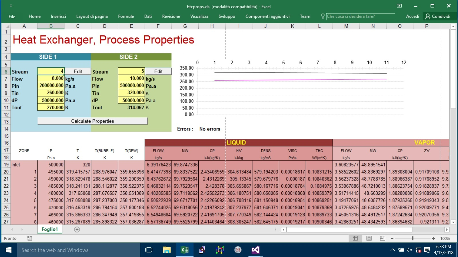
there was a Excel page showing how to calculate properties in different zones I attach a copy, you can examine the VBA code for details,
Prode Properties can export flows or you can calculate from (molar) phase fractions and molar weights of different fractions, see this VBA example
PF = StrLf(Stream)
If (PF > 0.000001) Then ' Liquid present ?
mw = StrLMw(Stream)
Cells(rpt + I, 6) = W * PF * mw / mwm ' Liquid Flow
and so on...
you can calculate mixture properties (density, viscosity, thermal conductivity etc.) in different ways,
Prode Properties exposes methods StrGD, StrLD etc. (there are about 300 methods...)
in this Excel VBA example the procedure calculates vapor properties as
Cells(rpt + I, 14) = StrGMw(Stream)
Cells(rpt + I, 15) = StrGCp(Stream)
Cells(rpt + I, 16) = StrZv(Stream)
Cells(rpt + I, 17) = StrGD(Stream)
Cells(rpt + I, 18) = StrGV(Stream)
Cells(rpt + I, 19) = StrGC(Stream)
of course different variants are possible (many methods available),
you can solve many different Flash Operations with Prode Properties, in this case (heat exchanger simulation) the procedure solves a operation with specified P and H but different alternatives are possible
![]() htcprops.xls 176.5KB
48 downloads
htcprops.xls 176.5KB
48 downloads
#111399 Steam To Carbon Ratio
 Posted by
on 03 October 2017 - 03:38 PM
Posted by
on 03 October 2017 - 03:38 PM
Hi,
In syngas plants (ammonia, hydrogen, methanol, etc.) the concepts are different. Steam to dry gas ratio (usually abbreviated as S/DG) is the ratio between molar flow rate of steam and gas, so it's steam flow rate divided dry gas flow rate. This ratio is use frequently at the inlet of shift reactors (HTS, high temperature shift, and LTS, low temperature shift), in particular to evaluate of the flow fed has enough steam as to prevent iron carbide formation in iron-based HTS catalysts.
Steam to carbon ratio is usually used to evaluate the amount of steam at the inlet of a steam reformer, and is the ratio between the steam and the carbon, in mole basis. Consider that C2H6 counts as 2 carbons, C3H8 as 3, etc. E.g. if you have a stream consisting of a mixture of 3000 mol/h of steam, 500 mol/h of C1, and 200 mol/h of C2, ethane counts twice as much (2 carbon moles), so in this case it would be 3000/(500+200*2) = 3.33. In this same case, the S/DG ratio would be simply (3000/700) = 4.28 (though in practice no HTS reactor operates with such a high value).
Theoretically speaking, in the case of a stream consisting of just steam and methane, S/DG and S/C ratio would be the same. In the case of a stream with only steam, methane, and some nitrogen, the S/DG ratio would differ from the S/C ratio. There are some other ratios used, such as the S/C ratio just for hydrocarbons (so you don't consider inorganic compounds such as CO or CO2) or the S/HCC ratio (you just consider HC C2+).
Hope it was clear enough 
Best regards
#107463 Design Of Distillation Column
Posted by
on 23 January 2017 - 11:57 AM
Mohammed:
To learn how to process design a distillation column you can do a variety of things:
- You can take a first year chemical engineering Unit Operations course in a university that offers such a study;
- You can purchase and study a book on the subject; some books are:
Douglas, James M., Conceptual Design of Chemical Processes, McGraw-Hill, 1988, pp. 453-457.
Kister, Henry Z., Distillation Design, McGraw-Hill, 1992, pp. 275-282.
Luyben, William L., "Introduction" in Practical Distillation Control (W.L. Luyben, ed.), Van Nostrand Reinhold, 1992, pp. 10-11.
McCabe, W.L., J.C. Smith, P. Harriott, Unit Operations of Chemical Engineering, 5th Edition, McGraw-Hill, 1993, pp. 560-568.
Seader, J.D. and Ernest J. Henley, Separation Process Principles, John Wiley, 1998, pp. 305-312. - You can study the material found in many web sites on the internet. One such site is Dr. Randel Price's (http://facstaff.cbu.edu/rprice/) and a sample of his lecture notes is attached.
7-Distillation - Principles.docx 41.13KB
136 downloads
8-Distillation II - Modeling.docx 43.81KB
108 downloads
9-Distillation III - Operating Equations.docx 51.76KB
103 downloads
10-Distillation IV - Calculations.docx 65.62KB
134 downloads
11-Distillation V - Ethalpy Balances.docx 39.63KB
95 downloads
12-Distillation VI - Enthalpy Concentration Methods.docx 63.35KB
86 downloads
13-Distillation VII - Equipment & Column Sizing.docx 56.11KB
132 downloads
14-Batch Distillation.docx 45.86KB
96 downloads

