Jump to content


Featured Articles

Check out the latest featured articles.

File Library

Check out the latest downloads available in the File Library.

New Article

Product Viscosity vs. Shear

Featured File

Vertical Tank Selection

New Blog Entry

Low Flow in Pipes- posted in Ankur's blog

- - - - -

Using Hot Glycol On Glycol Regeneration Train To Heat Coil Inside Sepa

meg glycol

This topic has been archived. This means that you cannot reply to this topic.
19 replies to this topic
Share this topic:
| More

#1 Dmitry

Dmitry

    Gold Member

  • Members
  • 180 posts

Posted 09 July 2015 - 05:14 AM

Hello All,


I will be very glad if you help me to find solution


We have Gas plant with Dew point unit with propane cycle. We use glycol - MEG for injection upstream chiller and heat exchangers.
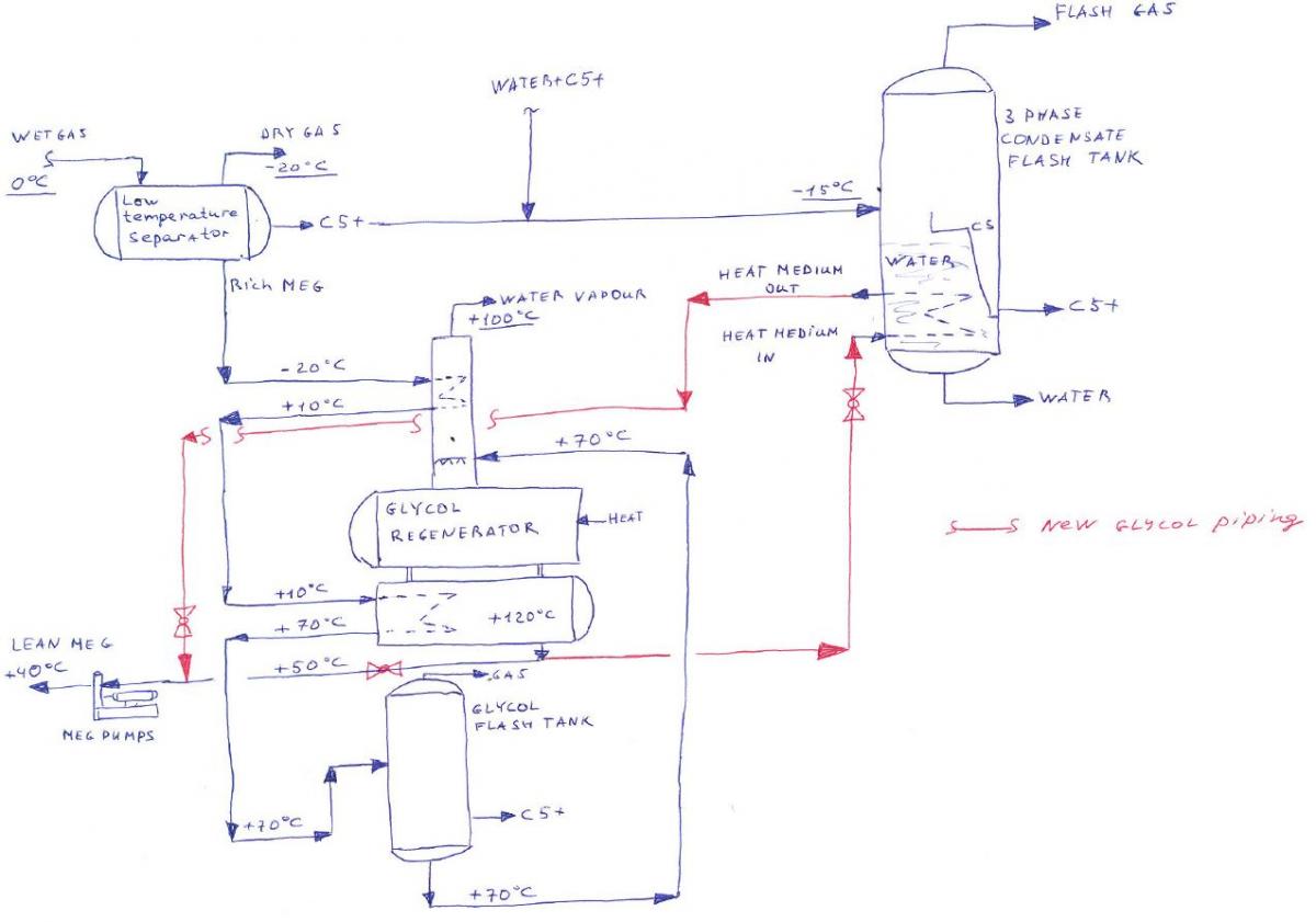
Cold condensate from 3 phase Low temperature separator goes to the 3 phase Glycol flash tank.
We have additional stream of mixture (water+C5) from upstream 2 phase separator.
On this 3 phase condensate flash tank we have installed internal heat medium coil, the purpose of it is
 
- To preheat bottom part of the vessel in winter time to prevent freezing
- To improve condensate degassing
 
The one problem is that we do not have any heat medium fluid.
 
There is one idea is to use heat from hot glycol and transfer it to the flash tank. Let's say can we take hot glycol downstream regenerator and send it through the internal coil inside flash tank and that return cold glycol to the pumps suction? We want to keep +20...+40 deg. C in flash tank.
 
Please see attached sketch for better understanding.
 
I did not run any calculations yet in Hysys.


Many thanks for any help.


Regards,

Dmitry

Attached Thumbnails

  • Glycol to heat V-240.JPG

Edited by Dmitry, 09 July 2015 - 05:20 AM.


#2 shan

shan

    Gold Member

  • ChE Plus Subscriber
  • 692 posts

Posted 09 July 2015 - 06:56 AM

How do you have -15 C water phase inside 3 Phase Condensate Flash Tank instead of ice?


#3 Dmitry

Dmitry

    Gold Member

  • Members
  • 180 posts

Posted 09 July 2015 - 08:05 AM

-15 deg C. - this is the temperature of incoming stream from Low temperature separator.
 
After mixing with another stream from 2 phase separator total temperature in 3 phase condensate flash tank is about 10 deg in night time and 20 deg C in day time.
 
Please note that we expect first winter for this equipment. So in winter when ambient temperature will be -20 we will have -20 inside vessel and water phase with instruments chambers will freeze

Edited by Dmitry, 09 July 2015 - 08:11 AM.


#4 shan

shan

    Gold Member

  • ChE Plus Subscriber
  • 692 posts

Posted 09 July 2015 - 08:43 AM

How do you cool the inlet wet gas from 0 C to -20 C without a heat exchanger?


#5 Dmitry

Dmitry

    Gold Member

  • Members
  • 180 posts

Posted 09 July 2015 - 08:54 AM

How do you cool the inlet wet gas from 0 C to -20 C without a heat exchanger?

Dear, I just shown Low temperature separator so you can see from where we have rich glycol feed into regeneration train. I did not show upstream gas/propane chiller, gas/gas heat exchanger since it's not have related to the current issue.


#6 shan

shan

    Gold Member

  • ChE Plus Subscriber
  • 692 posts

Posted 09 July 2015 - 10:50 AM

Why do you not recover -15 C cooling duty to your inlet gas?  If you don't show us the whole picture, how do you expect the best solution from us?  You may need to conduct a whole site pinch analysis to obtain the optimized heat transfer scheme. The pinch analysis will involve much more data than what you have posted here.


#7 Dmitry

Dmitry

    Gold Member

  • Members
  • 180 posts

Posted 10 July 2015 - 12:54 AM

Why do you not recover -15 C cooling duty to your inlet gas?  If you don't show us the whole picture, how do you expect the best solution from us?  You may need to conduct a whole site pinch analysis to obtain the optimized heat transfer scheme. The pinch analysis will involve much more data than what you have posted here.

Sorry but what do you mean about recover - 15 C cooling duty to inlet gas? 


#8 RockDock

RockDock

    Gold Member

  • Members
  • 257 posts

Posted 14 July 2015 - 01:36 PM

Dmitry,


This looks reasonable to me.


#9 Dmitry

Dmitry

    Gold Member

  • Members
  • 180 posts

Posted 14 July 2015 - 11:29 PM

Dmitry,


This looks reasonable to me.

This is what I expected, however how can I check it?


May be I can model it in Hysys.


I have inlet flow of water + condensate to the vessel, 10 m3/day with temperature let's say -15 deg. C. So I need to add heat to the the vessel to heat it to +25...+40 deg. C.

Using Hysys I can find heat flow required for this.


After I can use this heat flow to see what will be the outlet temperature og glycol, with max flow rate 20 m3/day and temperature 110 deg. C.

May be me it's too much hot glycol will be and I need to install valves to use part of glycol.


My thoughts is correct?


Dmitry


Edited by Dmitry, 14 July 2015 - 11:31 PM.


#10 ColinR33

ColinR33

    Gold Member

  • Members
  • 106 posts

Posted 17 July 2015 - 09:34 AM

Dmitry, we do this all the time, although in a slightly different manner, on dewpoint control units.  Your PFD does not appear to show everything, but I can say that using the lean MEG from the Regenerator to heat the Glycol/water phase in the Low Temperature Separator is commonly done, although it is supplied from the discharge of the MEG circulation pumps.  Using the stream from the suction of the MEG pumps will not work very well, if at all, as you have essentially no pressure available to circulate the hot MEG through the coil as the MEG Regenerator operates at essentially atmospheric pressure.   I have attached a quick sketch of how we usually do it.  Sizing the coil itself is kind of a black art, depends on the LTS temperature and size of the vessel/boot, and flow rate. I typically use a U value of 5-20 Btu/hr/ft2-F (sorry, you'll have to convert to SI units yourself).  The coil is typically 3/4" or 1" BWG 14 tube shaped by coiling it around a pipe.  ie. if the vessel/boot is  24" (610mm) dia we'd probably use a 14-16" (350-400mm) NPS pipe to couil the tube around - bear in mind the coil will "spring back" and end up a couple inches larger diameter than what you coiled it around.  For large vessels you can use a flat multipass coil.


HTH

Cheers

Attached Files

  • Attached File  PFD.pdf   36.62KB   432 downloads

Edited by ColinR33, 17 July 2015 - 09:36 AM.


#11 RockDock

RockDock

    Gold Member

  • Members
  • 257 posts

Posted 17 July 2015 - 09:34 AM

Since it is glycol, I would use ProMax to get a good estimate of the heat flow. ProMax would be particularly helpful in knowing the BTEX absorbed into the MEG. BTEX can be soluble in glycol. I've only ever seen ProMax model that well.


That said, this will all depend on the how heavy your wet gas is and the performance of your inlet separator. If it has a lot of heavy components, you may not have enough glycol to provide the heat you desire. I think this should work in theory. You can model it and see if you have enough glycol for the process. You can always regulate the pressure of the flash tank based of the amount of glycol you have for your heating medium.


#12 Dmitry

Dmitry

    Gold Member

  • Members
  • 180 posts

Posted 11 August 2015 - 02:59 AM

Dmitry, we do this all the time, although in a slightly different manner, on dewpoint control units.  Your PFD does not appear to show everything, but I can say that using the lean MEG from the Regenerator to heat the Glycol/water phase in the Low Temperature Separator is commonly done, although it is supplied from the discharge of the MEG circulation pumps.  Using the stream from the suction of the MEG pumps will not work very well, if at all, as you have essentially no pressure available to circulate the hot MEG through the coil as the MEG Regenerator operates at essentially atmospheric pressure.   I have attached a quick sketch of how we usually do it.  Sizing the coil itself is kind of a black art, depends on the LTS temperature and size of the vessel/boot, and flow rate. I typically use a U value of 5-20 Btu/hr/ft2-F (sorry, you'll have to convert to SI units yourself).  The coil is typically 3/4" or 1" BWG 14 tube shaped by coiling it around a pipe.  ie. if the vessel/boot is  24" (610mm) dia we'd probably use a 14-16" (350-400mm) NPS pipe to couil the tube around - bear in mind the coil will "spring back" and end up a couple inches larger diameter than what you coiled it around.  For large vessels you can use a flat multipass coil.


HTH

Cheers

Thanks,  

We already use heat from glycol  to heat Glycol/water phase in the LTS on Dew point unit as you shown on your PFD, this is the standart solution for these units. 


My question if we can use heat from this glycol to heat water in the  3-phase second stage condensate flash drum?


I added this info on your PFD, so you can see what is my idea.


If we will take all heat in the condensate flash drum, glycol may go to the Dew point unit already cold, and it will not preheat water Glycol/water phase in the LTS on Dew point unit...


Dmitry

Attached Files


Edited by Dmitry, 11 August 2015 - 03:08 AM.


#13 ColinR33

ColinR33

    Gold Member

  • Members
  • 106 posts

Posted 11 August 2015 - 12:06 PM

In theory, yes it could be done, but as you note, there are some potential problems with overcooling the glycol.  Another option is to add a small pump to pump hot EG directly from the regenerator surge section to the C5+ flash drum coil and then back into the reboiler section of the regen.  This works if you have extra heat duty available in the regen (we've done similar things in the past).  We've used a little Grundfos or Deanline pump for this service.


#14 Dmitry

Dmitry

    Gold Member

  • Members
  • 180 posts

Posted 12 August 2015 - 12:15 AM

In theory, yes it could be done, but as you note, there are some potential problems with overcooling the glycol.  Another option is to add a small pump to pump hot EG directly from the regenerator surge section to the C5+ flash drum coil and then back into the reboiler section of the regen.  This works if you have extra heat duty available in the regen (we've done similar things in the past).  We've used a little Grundfos or Deanline pump for this service.

Hello Colin,


Thanks for the informaion, so how you done this? How you operated this pumps? Do you have manual valves or some control valves to keep required flow of hot glycol? If you have PFD or P&ID it will help.


We have about 50% availblle duty on regenerator so it's good!


Thanks again!


Edited by Dmitry, 12 August 2015 - 12:16 AM.


#15 ColinR33

ColinR33

    Gold Member

  • Members
  • 106 posts

Posted 12 August 2015 - 09:07 AM

We just used a small pump with manual valves and let it recirculate, no need for anything fancy, just need a globe valve to get some backpressure on the pump discharge.  Get it set up and let it run.  The little Deanline and Grundfos pumps can happily operate as low as 1-5 USGPM.  Suction block valve & strainer, discharge pressure gauge, check valve, isolation valve and manual globe valve, isolation and bypass valves on coil, then back to regen.  Adjust the flow to get the temperature you want in the coil, use the PI to check where you are on the pump curve.  If you really want, install a local flow meter.  Thats it.  Cheers.


#16 Dmitry

Dmitry

    Gold Member

  • Members
  • 180 posts

Posted 13 August 2015 - 08:46 AM

We just used a small pump with manual valves and let it recirculate, no need for anything fancy, just need a globe valve to get some backpressure on the pump discharge.  Get it set up and let it run.  The little Deanline and Grundfos pumps can happily operate as low as 1-5 USGPM.  Suction block valve & strainer, discharge pressure gauge, check valve, isolation valve and manual globe valve, isolation and bypass valves on coil, then back to regen.  Adjust the flow to get the temperature you want in the coil, use the PI to check where you are on the pump curve.  If you really want, install a local flow meter.  Thats it.  Cheers.

Yes, you right, the hot glycol  should be routed to the coil with circulation pump. It will not work if I just take glycol from regenerator outlet and sent it to coill. However a per your option we require to install little Deanline and Grundfos pumps.

What about if we will take glycol downstream of existing glycol pump. I am worry that pressure on discharge is 50 bar, and coli in the new vessel design for the 18 bar. So this option is bad...


#17 ColinR33

ColinR33

    Gold Member

  • Members
  • 106 posts

Posted 14 August 2015 - 05:04 PM

Either way you have to make sure you have relief capacity available in case of coil rupture (like tube rupture case in a heat exchanger, whether the coil has the higher pressure (flow into vessel through rupture) or the vessel (flow from vessel into coil through rupture).  Also, taking from downstream of the inection pumps you have to be careful you don't over cool teh glycol as was discussed earlier.


#18 Dmitry

Dmitry

    Gold Member

  • Members
  • 180 posts

Posted 17 August 2015 - 12:44 AM

Either way you have to make sure you have relief capacity available in case of coil rupture (like tube rupture case in a heat exchanger, whether the coil has the higher pressure (flow into vessel through rupture) or the vessel (flow from vessel into coil through rupture).  Also, taking from downstream of the inection pumps you have to be careful you don't over cool teh glycol as was discussed earlier.

The internal coil designed with 150# piping the same as vessel, what we need to preheat. Pressure on injections pumps could be 40-60 bar (piping 600#), since this is gas plant pressure. Now I see that taking hot glycol from injection pumps discharge will not work due to this reason and due to requirements to have hot glycol on LTS as you mensioned. 


I will look closer for the option with installation of new small circulation pump as you propose, taking glycol from regenerator

Do you have info what is the model of you similar pump? Could you share P&ID with your glycol system and this pump?


Many thanks!

Dmitry


#19 ColinR33

ColinR33

    Gold Member

  • Members
  • 106 posts

Posted 21 August 2015 - 01:19 PM

Like I said, a Dean 3/4DL or a little Grundfos will do the trick and very simple system as I laid out in post #15.


#20 Dmitry

Dmitry

    Gold Member

  • Members
  • 180 posts

Posted 14 September 2015 - 11:15 PM

Like I said, a Dean 3/4DL or a little Grundfos will do the trick and very simple system as I laid out in post #15.

Thanks!


Similar Topics