FB
FB

Screw Feeder Auger Shafts
09 August 2010
Analysis of a broken screw feeder shaft on a granular Copper Sulphate Bagging Hopper Feed Screw
Are your screw feeder and trough screw conveyor auger shafts snapping in half? If you have rotating shafts breaking at the centre of the span then you quite likely have a metal fatigue problem. Read more in our blog posting below.
The 316L stainless steel screw feeder shaft on a 3200mm long, 260mm diameter, 1:1 pitch flight screw broke in the middle. The shaft was 50mm Schedule 40 316L stainless steel pipe. The screw flight was 6mm thick 316L plate stitch welded to the shaft. The screw had been replaced new only 4 weeks prior. The screw was removed from the trough in two pieces and the break was at the middle of the screw. The break was generally square to the shaft.
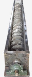
Analysis of the forces on the auger shaft indicated that it was adequately sized for the job. Torque on the shaft was only 300Nm. Motor power was also low at 0.37kW (1/2 horse power). The only remaining likelihood to explain the breakage was fatigue failure.
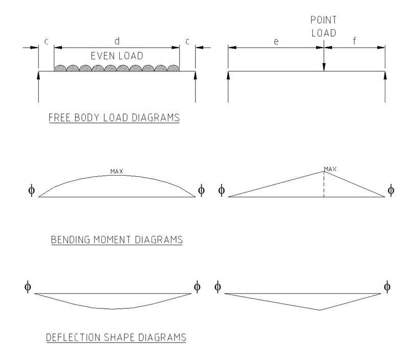
It was noted that the inside wall of the trough was coated in copper sulphate crystal build-up. Damp product had accumulated at the bottom of the trough and formed into a thick crust. When the build-up was scrapped-off the thickness of the crust was 10mm. The crust produced a combination of uniform loading along the shaft and high localised load along the middle section as the shaft was forced to bend over the crust. The types of combined load seen by the auger shaft is depicted in the drawing below.
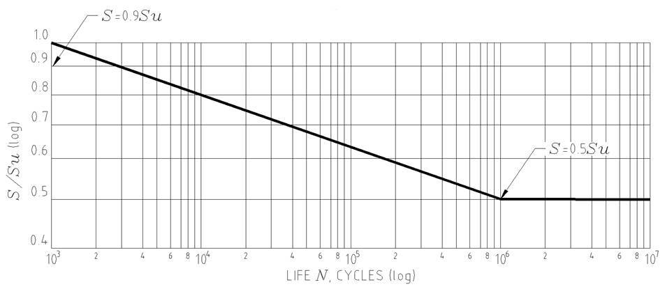
To check if the failure was due to fatigue from the crust causing the shaft to deflect while it was rotating, it was necessary to prove that the stresses at the mid point of the shaft had gone above the infinite life fatigue limit. A fatigue diagram for wrought steel is shown below and highlights that if total stresses are kept below the fatigue life line there apparently is an infinite working life.
The analysis starts with a simplified sketch of the load conditions experienced by the shaft. It is basically a simply supported round annular beam fixed in-place by the bearings at each end. This assumption made the mathematics required for the analysis simpler and based on standard stress formulae. The 6mm thick stainless steel flights wound around the pipe contributed to stiffening the auger. The stiffening effect of the flight was neglected for the sake of simplicity in identifying whether bending stress was the likely cause of the break.
By combining the deflection formula for the standard beam with the bending stress formula it was possible to relate the stress in the pipe to the deflection of the beam. The maximum stress was always at the centre of the supported section. By picking various deflections the resulting stresses could be calculated. The results are listed in the Table below:
Deflection mm | Stress MPa |
1 | 8.2 |
10 | 82 |
20 | 164 |
30 | 246 |
316L stainless steel has a 0.2 percent yield stress of 240MPa and a ultimate tensile stress of 550MPa. In the case of the shaft failure the deflection was about 10mm and the corresponding bending stress was well within the yield stress. The shaft did not fail because of bending stresses alone. However when the rotating action of the stainless steel screw is superimposed on the bending effect caused by the built-up crust, the situation becomes one of cyclic loading and metal fatigue becomes a major factor to add to the effect of bending. As a steel wire quickly snaps from fatigue when bent and worked to-and-fro, a rotating bent stainless steel shaft can breaking from working in a short time.
Metal undergoing cyclic loading will fail if the stress cycles above its fatigue endurance limit curve often enough. The endurance curve can be approximated from the ultimate tensile stress (Su) by taking half its value at one million cycles on a log-log plot and connecting the two points by a line. Provided the stress is below the flat portion of the curve the part will supposedly last indefinitely under the fluctuating load. This implies the infinite life stress for the shaft to be about 300MPa. The calculated imposed stress was below that value.
Additional to combined fluctuating fatigue stress from the rotating action of the shaft and the bending stress there are stress concentrations present at the stop and start of the stitch welds holding the flights to the shaft. Such defects in the metal as under-cuts and inclusions greatly lower the stress value at which stress cracks start to develop.
The combined effects of all these factors made the mid-point stitch weld the most stressed location. It was likely that once a stress crack developed from a weld imperfection it continued to grow rapidly under the cyclic load until the shaft failed.
This mode of failure, where a rotating shaft breaks at the midpoint between supports, is a classic combined bending, stress concentration and fatigue stress failure. If this occurs with your equipment it is necessary to determine what is causing the shaft to bend and remove that problem. If there are parts welded to the shaft look closely at the weld quality, particularly under-cuts, porosity and inclusions. If necessary grind the poor section of weld material out and remake the weld. Stress relieve the repair to remove the new internal stresses causes by the weld remake.