 FB
FB

Safety Integrity Level (Sil) Definition And Brief Explanation
29 March 2015
Dear All,
Most young process engineers have heard the term SIL but not got involved in what SIL is all about. In fact, there is a misconception among many younger process engineers that SIL is solely related to the advanced "Control & Automation" part of a process plant and process engineers need not get involved in a detailed SIL study or SIL review except for providing process data for the instrumentation under SIL study.
This is far from the truth. Process engineers need to be an integral part of any SIL review or SIL study because the basis or starting point of any SIL study is proper evaluation and finalization of the "Basic Process Control System" (BPCS) based on process studies / reviews such as "Design Review" and "Hazard & Operability Studies" (HAZOP).
SIL studies and SIL allocation for any process plant is a logical step ahead of the BPCS for safe and reliable plant operation.
Now, that I have explained how it is important for process engineers to be part of a SIL study exercise, let us get to the definitions of various terms and explanation of the methodology of SIL.
Some basic terms:
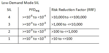
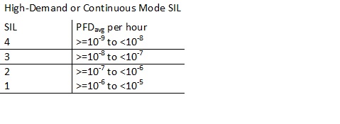
1. Probability of Failure on Demand (PFD): It It is a measure of safety system performance in terms of the Probability of Failure on Demand (PFD). It is expressed as a negative exponential of 10, for example, 10-5 .
2. Risk Reduction Factor: This is the inverse of of the POF and provides the reduction in risk by implementation of a SIL level to any critical safety-related instrumentation.
3. Safety-Instrumented Systems: It is a process plant instrument system which is designed to prevent or mitigate hazardous events by taking a process to a safe state when predetermined conditions are violated. Other common terms for SIS are safety interlock systems, emergency shutdown systems (ESD), and safety shutdown systems (SSD).
SIL evaluation is done for Safety-Instrumented Systems (SIS). Each SIS has one or more Safety Instrumented Functions (SIF). To perform its function, a SIF loop has a combination of logic solver(s), sensor(s), and final element(s). Every SIF within a SIS will have a SIL level. These SIL levels may be the same, or may differ, depending on the process. It is a common misconception that an entire system must have the same SIL level for each safety function.
SIL Levels (as per IEC 61508):
There are four discrete integrity levels associated with SIL: SIL 1, SIL 2, SIL 3, and SIL 4. The higher the SIL level, the higher the associated safety level, and the lower probability that a system will fail to perform properly. As the SIL level increases, typically the installation and maintenance costs and complexity of the system also increase. Specifically for the process industries, SIL 4 systems are so complex and costly that they are not economically beneficial to implement. Additionally, if a process includes so much risk that a SIL 4 system is required to bring it to a safe state, then there is a fundamental problem in the process design that needs to be addressed by a process change or other non-instrumented method.
The identification of risk tolerance is subjective and site-specific. The owner / operator must determine the acceptable level of risk to personnel and capital assets based on company philosophy, insurance requirements, budgets, and a variety of other factors. A risk level that one owner determines is tolerable may be unacceptable to another owner. Many well-known operating companies have their in-house guidelines / standards for assigning SIL levels for specific SIS and for a given type of process plant / unit.
As part of the engineering design cycle, SIL or SIS studies are conducted in a manner similar to other studies such as Design Review & HAZOP. The SIL or SIS study basic prerequisite is, availability of P&IDs and Plant Operation / Control / Safeguarding philosophy, which have been updated to incorporate all process design and HAZOP review comments.The SIL or SIS study is jointly driven by the process engineering and Control & Automation (Instrumentation) engineering group. A HSE engineer also plays an important part in this study / review. Based on the recommendations and report of the SIS study, SIL levels are assigned to various SIS systems in the process plant and instrument system architecture for these SIS systems defined.
The finer details of how the system architecture for the SIS needs to be constructed is handled by the Instrumentation Engineer and is beyond the scope of this blog article.
A basic explanation on SIL is also provided on the links provided below:
http://en.wikipedia....Integrity_Level
http://www.enggcyclo...ity-levels-sil/
A google search will provide many more articles related to SIS/SIL.
Hope this blog article helps process engineers to understand the basics of SIL and SIS. Looking forward to comments from the reader's of my blog.
Regards,
Ankur.


Thanks for the post. It is very good to have this kind of blog entries.
Just a small correction to the sentence "Every SIF within a SIS will have a SIL level".
If the consequence rating is acceptable with a non SIL-rated function, there is no need to assign any SIL level to the SIF.