Search Results
By content type
By section
-
Steam Tracing with MS Excel
Heat tracing is used to prevent heat loss from process fluids being transported in process fluid pipes, when there is risk of damage to piping, or interference with operation such as fouling or blockage, caused by the congealing, increase in viscosity, or separation of components, in the fluid below certain temperatures, or when there is risk of formation of corrosive substances or water due to condensation in corrosive services. This prevention of heat loss is accomplished by employing electrical tracing, or steam tracing, and insulating both the process fluid pipe and the tracer together, using appropriate insulation lagging, in an attempt to minimise heat loss from the pipe and tracer to their surroundings.
{parse block="google_articles"}The existing software that was used to design steam tracing had to be evaluated in terms of its accuracy and reliability, as problems associated with steam tracing designed with the existing software have occurred in the past. A software simulation had to be designed that could compare theoretical inputs and outputs with that of an existing simulation used to design steam tracing, as well as compare it to existing installed steam tracing, in order to determine where improvements in the software could be made.
The new software had to use the outputs from the existing software as inputs and its outputs had to correspond to the inputs of the existing software. Other important evaluations were also included in the new software.
Theory
The term “Heat Tracing†is inclusive for two methods used in the conservation of temperature. The first method is known as electrical heat tracing, and the second is known as steam tracing. Electrical heat tracing may be described as an insulated electrical heating cable, which is spiralled around the process fluid pipe, after which the pipe and tracing is insulated with the appropriate type and thickness of insulation lagging material. While this method of heat tracing may be installed with relative ease compared to steam tracing, it is more expensive, and poses several risks. The most important of these, being the risk of electric spark, which may cause electric shock or ignite flammable substances resulting in explosions or fire. If electrical heat tracing is not carefully controlled, there is also the possibility that the cable could overheat and damage the pipe or insulation. This also renders the tracing cable unusable and the cable needs to be replaced.
In order to follow the theory, download the Nomenclature from the Downloads section.
Download the spreadsheet developed with the method presented here in our Downloads Section
Steam tracing is described by attaching a smaller pipe containing saturated steam, also known as the “tracerâ€, parallel to the process fluid pipe. The two pipes are then also insulated together with the specified insulation and jacketed if necessary. Steam tracing is more labor intensive to install than electrical heat tracing, but there are very few risks associated with it. The temperature of the tracer also cannot exceed the maximum saturation temperature of the steam, as it operates at specific steam pressures.
Steam tracing may be done in one of two ways. Bare steam tracing is the most popular choice as it is fairly easily installed and maintained and it is ideally suited to lower temperature requirements. It is simply composed of a half inch or three quarters of an inch pipe attached to the process fluid pipe by straps and both pipes are then insulated together. The other available option is to make use of cemented steam tracing, during which heat conductive cement is placed around the steam tracer running parallel to the process fluid pipe, (shown in figure 1b), in an attempt to increase the contact area available for heat transfer, between the tracer and the process fluid pipe.
It is necessary to foster a better understanding of the heat loss distribution through an insulated pipe containing steam tracing, before continuing the discussion. For this purpose, detailed diagrams depicting the cross-sections of the two types of tracing methods are given below, in Figures 1a and b:
Because the area around the process fluid pipe and tracer cannot be accurately described simply by assuming perfect cylindrical geometry, provision had to be made for a realistic impression of the true geometry. Detailed derivations of formulas are included in Appendix 1. Heat transfer across a surface occurs according to the following equation: (Coulson & Richardson, 1999:634-688)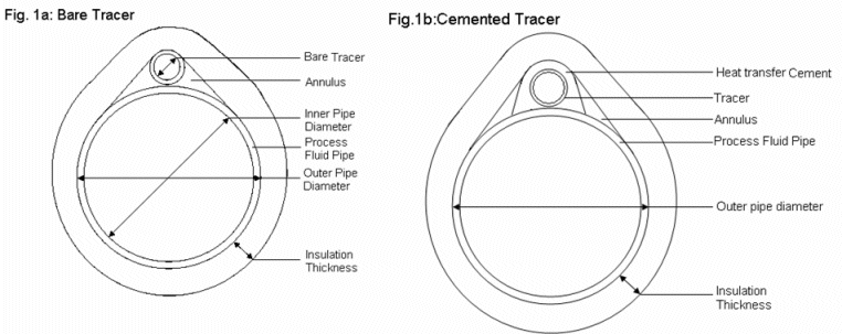
Figures 1a and 1b: Bare versus Cemented Tracer
The following equations were derived in determining the different areas across which heat transfer occurs:
Eq. (1)
For bare tracing, the following formulas were derived:
Eq. (2) 
Eq. (3) 
Eq. (4) 
Eq. (5) 
Eq. (6) 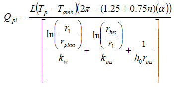
Eq. (7) 
Eq. (8) 
Eq. (9) 
Eq. (10) 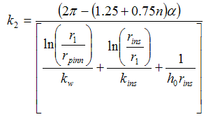
Eq. (11)
The following equation was used to determine the hottest surface temperature for bare tracing: (Le Roux, D.F. (1997) “Thermal Insulation and Heat Tracingâ€, Guideline presented by D.F. le Roux, Secunda):
Eq. (12) 
Eq. (13) 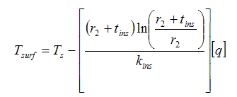
Eq. (14)
For cemented tracing, the following formulas were derived:
Eq. (15) 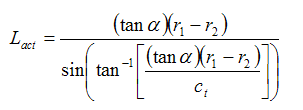
Eq. (16) 
Eq. (17) 
Eq. (18) 
Eq. (19) 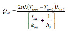
Eq. (20) 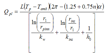
Eq. (21) 
Eq. (22) 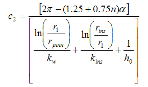
Eq. (23) 
Eq. (24)
The following equation was used to determine the hottest surface temperature for cemented tracing:
Eq. (25)
where:
Eq. (26) 
Eq. (27)
- May 30 2012 01:47 PM
- by adelange

 FB
FB

