 FB
FBChemical and Process Engineering Resources

Making polymers is a fantastic science.  Then there is the matter of shaping the plastic into useful objects....another fantastic science. One of the most common methods of shaping plastic resins is a process called injection molding. Injection molding is accomplished by large machines called injection molding machines.
The resin is injected into the mold by a reciprocating screw or a ram injector. The reciprocating screw apparatus is shown above. The reciprocating screw offers the advantage of being able to inject a smaller percentage of the total shot (amount of melted resin in the barrel). The ram injector must typically inject at least 20% of the total shot while a screw injector can inject as little as 5% of the total shot. Essentially, the screw injector is better suited for producing smaller parts.
Â
 | Â | 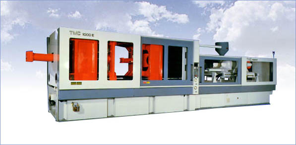 | Â | |
| Figure 1: Diagram of Injection Molding Machine | Â | Figure 2: Photo of Injection Molding Machine | Â | Figure 3: Diagram of Heated Screw Conveyor |
The mold is the part of the machine that receives the plastic and shapes it appropriately. The mold is cooled constantly to a temperature that allows the resin to solidify and be cool to the touch. The mold plates are held together by hydraulic or mechanical force. The clamping force is defined as the injection pressure multiplied by the total cavity projected area. Typically molds are overdesigned depending on the resin to be used. Each resin has a calculated shrinkage value associated with in.
Some Typical Complications
Burned or Scorched Parts: Melt temperature may be too high. Polymer may be becoming trapped and degrading in the injection nozzle.  Cycle time may be too long allowing the resin to overheat.
Warpage of Parts: Uneven surface temperature of the molds. Non-uniform wall thickness of mold design.
Surface Imperfections: Melt temperature may be too high causing resin decomposition and gas evolution (bubbles). Excessive moisture in the resin. Low pressure causing incomplete filling of mold.
Incomplete Cavity Filling: Injection stroke may be too small for mold (ie. not enough resin is being injected). Injection speed may be too slow causing freezing before mold is filled.
Diagrams courtesy of Plastics: Materials and Processing, Prentice Hall by A. Brent Strong
1 Comments