Chemical and Process Engineering Resources
Cooling Towers: Design and Operation Considerations
Nov 08 2010 12:50 PM | Chris Haslego
Preliminary Cooling Tower Design
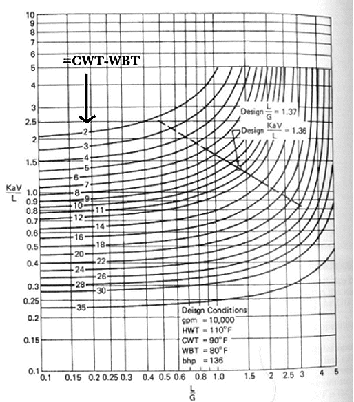
Although KaV/L can be calculated, designers typically use charts found in the "Cooling Tower Institute Blue Book" to estimate KaV/L for given design conditions.
- A change in wet bulb temperature (due to atmospheric conditions) will not change the tower characteristic (KaV/L)
- A change in the cooling range will not change KaV/L
- Only a change in the L/G ratio will change KaV/L
 |
| Figure 7: A Typical Set of Tower Characteristic Curves |
The straight line shown in Figure 7 is a plot of L/G vs KaV/L at a constant airflow. The slope of this line is dependent on the tower packing, but can often be assumed to be -0.60. Figure 7 represents a typical graph supplied by a manufacturer to the purchasing company. From this graph, the plant engineer can see that the proposed tower will be capable of cooling the water to a temperature that is 10 °F above the wet-bulb temperature. This is another key point in cooling tower design.
Cooling towers are designed according to the highest geographic wet bulb temperatures. This temperature will dictate the minimum performance available by the tower. As the wet bulb temperature decreases, so will the available cooling water temperature. For example, in the cooling tower represented by Figure 7, if the wet bulb temperature dropped to 75 °F, the cooling water would still be exiting 10 °F above this temperature (85 °F) due to the tower design.
Below is the summary of steps in the cooling tower design process in industry. More detail on these steps will be given later.
- Plant engineer defines the cooling water flowrate, and the inlet and outlet water temperatures for the tower.
- Manufacturer designs the tower to be able to meet this criteria on a "worst case scenario" (ie. during the hottest months). The tower characteristic curves and the estimate is given to the plant engineer.
- Plant engineer reviews bids and makes a selection
Other Design Considerations
Once a tower characteristic has been established between the plant engineer and the manufacturer, the manufacturer must design a tower that matches this value. The required tower size will be a function of:
- Cooling range
- Approach to wet bulb temperature
- Mass flowrate of water
- Web bulb temperature
- Air velocity through tower or individual tower cell
- Tower height
Approach to Wet Bulb (0F) | Cooling Range (0F) | Tower Height (ft) |
| 15-20 | 25-35 | 15-20 |
| 10-15 | 25-35 | 25-30 |
| 5-10 | 25-35 | 35-40 |
Other design characteristics to consider are fan horsepower, pump horsepower, make-up water source, fogging abatement, and drift eliminators.
Operation Considerations
Water Makeup
Water losses include evaporation, drift (water entrained in discharge vapor), and blowdown (water released to discard solids). Drift losses are estimated to be between 0.1 and 0.2% of water supply.
| Evaporation Loss = 0.00085 * water flowrate(T1-T2) | Eq. (5) |
| Blowdown Loss = Evaporation Loss/(cycles-1) | Eq. (6) |
| Total Losses = Drift Losses + Evaporation Losses + Blowdown Losses | Eq. (7) |
Cold Weather Operation
Even during cold weather months, the plant engineer should maintain the design water flowrate and heat load in each cell of the cooling tower. If less water is needed due to temperature changes (ie. the water is colder), one or more cells should be turned off to maintain the design flow in the other cells. The water in the base of the tower should be maintained between 60 and 70 0F by adjusting air volume if necessary. Usual practice is to run the fans at half speed or turn them off during colder months to maintain this temperature range.
References
- The Standard Handbook of Plant Engineering, 2nd Edition, Rosaler, Robert C., McGraw-Hill, New York, 1995
- Perry's Chemical Engineers' Handbook, 6th Edition, Green, Don W. et al, McGraw-Hill, New York, 1984

 FB
FB

3 Comments
Thank you for your valuable presentation.