 FB
FBChemical and Process Engineering Resources

Flow Through Orifice Plates in Compressible Fluid Service at High Pressure Drop
Nov 08 2010 01:40 PM | dkirk in Safety and Pressure Relief

Cunningham Method
Experiments carried out by RG Cunningham and published by ASME in July 1951 clearly demonstrated that the assumption of a fixed limit to critical flow through thin square edged orifice plates is not correct.
Cunningham’s work included tests with air and steam with the results and conclusions presented as tables, charts and formulas. Limited information is provided for the tests with steam.
The results demonstrated that with suitable corrections to the Expansion Factor Y, the formula for non-critical flow should be used in all cases for thin square edge orifice plates. Critical flow can, however, be expected for thick orifice plates with t ? 6 x the orifice diameter.
Cunningham’s paper also includes an equation for the Flow Coefficient, though this appears to provide only a rough approximation and other methods may be preferable (e.g. AGA 3):
| Eq. (7) |
The ASME formula for Y was shown to be appropriate only down to P2 = 0.63 x P1; (not the normally expected 0.528 from thermodynamic analysis) at which point there is a distinct discontinuity in the flow to lower discharge pressures. Continued use of the ASME formula for Y produces errors of up to 12% if used for lower discharge pressures. Alternative methods reviewed involved errors of up to 40%.
Analysis of the Cunningham data suggests the following formula may be used to determine Y for flange taps at discharge pressures below 0.63 x P1:
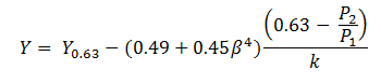 | Eq. (8) |
where Y0.63 is Y from the ASME formula at P2 = 0.63 x P1.
The use of a formula similar to the form of the ASME equation is based on an expectation that there is a reasonable probability that the flow to lower pressures will be similarly sensitive to the same geometric and process parameters. The use of ? (beta) to the 4th power provides a reasonable fit to the experimental data. Since the relationship between Y and the pressure ratio is linear the (0.63-P2/P1) component is clearly appropriate. The inclusion of k as a direct divisor in the equation is less obvious and difficult to confirm from the limited data available.
The chart first chart below is extracted directly from the Cunningham report and clearly shows the discontinuity at a pressure ratio of 0.63 and the potential for error if the ASME formula is used beyond this point. The chart second chart below is generated using the proposed method.
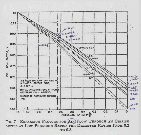 |  |
| Figure 1: Results with Cunningham Method | Figure 2: Results with Proposed Method |
Download additional information on the derivation of this method in our Article Supplements Repository
References
- Technical Paper 410M, Crane, 1983
- Orifice Meters with Supercritical Compressible Flow, RG Cunningham – ASME, July 1951
- Perry’s Chemical Engineering Handbook – 7th Edn – RH Perry, DW Green
- Flow Measurement Engineering Handbook, 3rd Edn – RW Miller
(Note: formula 9.58 is correct only for air with ß = 0.15 and could be replaced with the method proposed above.)
0 Comments