Chemical and Process Engineering Resources

Rupture Disks for Process Engineers - Part 5
Nov 08 2010 01:30 PM | pleckner in Safety and Pressure ReliefRelief Valve Sizing
Inlet Line
The relief valve inlet line is defined as the piping between the inlet to the system (e.g. the inlet to a vessel nozzle) and the relief valve inlet flange. Sizing this inlet line is a trial-and-error procedure. First, the process engineer chooses a line size using guidelines set by code; code requires that the flow area of the line and all associated piping components be at least equal to the relief valve inlet flow area. Then, using
Outlet Line (Tail Pipe) Sizing OverviewÂ
The sizing of the tail pipe is done in a similar manner to that outlined above for the inlet line. The process engineer first chooses a pipe size. Then, using accepted fluid flow equations (e.g. Darcy for liquids, Isothermal or Adiabatic for gas/vapor and DIERS for two-phase) and the same certified flow capacity as used for the inlet line, a built-up (variable) backpressure is calculated. The built-up backpressure is converted to a percentage of the relief valve set pressure and is then compared to some maximum value that is set by the particular relief valve manufacturer. For example, tail pipes on conventional style relief valves would be sized such that the built-up (variable) backpressure does not exceed 10% of the relief valve set pressure. For balanced bellows style relief valves, tail pipes would be sized such that the built-up (variable) backpressure does not exceed 30% to 55% of the relief valve set pressure, depending on manufacturer. If the calculated percentage is less than or equal to these maximums, the line size is acceptable. If the calculated percentage is greater, the line size may or may not be acceptable. This is because the only requirement of code is that the built-up backpressure does not affect the relief valve's ability to relieve the required amount of flow necessary to protect the system. Built-up backpressures greater than the stated maximums require a de-rating of the relief valve based on curves developed by the manufactures. As long as the de-rated valve can still relieve the required relieving flow, the line size chosen is acceptable. If not, then the line is too small.
Now that we've sized the relief valve in the relief valve/rupture disk combination, what about sizing the rupture disk? Actually, we already did!
The Rupure Disk
Sizing
You will recall from Part 2 of this series that sizing the rupture disk is a two-part procedure. First, determine how much flow the rupture disk needs to pass. Then determine how big it needs to be.
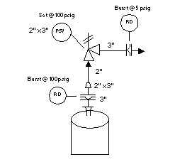
Both criteria have been met with the relief valve sizing. How much flow? The rupture disk must be able to pass the certified flow capacity of the relief valve. How big? The rupture disk must be big enough so that its contribution to the frictional losses does not pose a significant impact on the ability of the relief valve to protect the system. For a rupture disk installed in the inlet line, the rupture disk's net flow area must be at least equal to the relief valve inlet flow area; it may be larger. Also, its contribution to the non-recoverable frictional losses should be minimal so as to ensure that the piping system meets the 3% Rule. Indeed, you may even find that the rupture disk must be one-size larger than the inlet to the relief valve in order to satisfy the 3% Rule. For example (Figure 2), a 2" x 3" relief valve (2" being the inlet flange size and 3" being the outlet flange size) may require a 3" rupture disk!
 |
| Figure 2: 2" x 3" Relief Valve |
 |
| Figure 3: Rupture Disk is Larger than Outlet Flange |
For a rupture disk installed in the tail pipe, the rupture disk size should be large enough so that it contributes minimally to the built-up backpressure. And again, the rupture disk may very well have to be a size larger than the relief valve outlet flange to accomplish this (Figure 3).
For both the inlet line and tail pipe calculations, the rupture disk's certified Kr is used in the friction loss calculations.
What the Code Says About...
Bursting
The stamped (certified) burst pressure of the rupture disk must be between 90% and 100% of the relief valve set pressure. Also, the bursting of the rupture disk and the opening of the relief valve must be essentially coincident with each other.
Backpressure
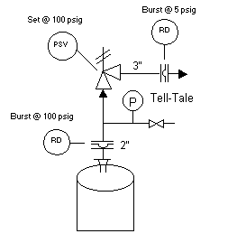
When specifying a rupture disk that will be used upstream of a relief valve, it is expected that the superimposed backpressure will be constant and essentially zero (after all, there should be nothing between the rupture disk and the relief valve but some trapped air). However, over time the rupture disk may leak for a variety of reasons. This leakage will cause a build-up of pressure between the rupture disk and the relief valve. As we saw in Part 4, unexpected backpressure on the rupture disk will change the relieving pressure of the vessel or system. To guard against this, code requires the use of a "tell-tale". The "tell-tale" must consist of, as a minimum, a pressure gage and a vent line inserted between the rupture disk and the relief valve. Typically, a valve is put into the vent line for a more controlled design (Figure 4). In installations where the rupture disk holder is close-coupled with the relief valve, this system is inserted into a chamber within the holder. Note that a better tell-tale design would include a pressure transmitter with an alarm as well as the pressure gage.
Â
 |
| Figure 4: Valve in Vent Line |
For rupture disks installed after the relief valve, the disk's bursting pressure must not be affected by any backpressure affects nor can there be allowed a pressure build-up between the relief valve and rupture disk that may affect the operation of either device. A "tell-tale" should be used to protect against pressure build-up between the devices due to leaks through the relief valve. The only way to protect against backpressure affects is to make sure the superimposed backpressure is well defined and constant (see Part 4 of this series).
Obstructions
A bursting rupture disk must not cause obstruction of the relief valve or the relief piping. Therefore, the non-fragmenting rupture disk is used in this service. This disk will break cleanly, with no material being broken off.

 FB
FB

0 Comments