Chemical and Process Engineering Resources

Rupture Disks for Process Engineers - Part 6
Nov 08 2010 01:30 PM | pleckner in Safety and Pressure ReliefFinal Thoughts
Liquids
Liquids are treated the same way as gases/vapors in all aspects of determining those two questions, how much and how big. However, do not forget to take the hydraulic pressure into account. Pressure in the system will not be equal throughout. If the rupture disk is installed on a nozzle or in a pipe at the top of a liquid filled vessel, the pressure at the rupture disk will be less than all points below it. If the rupture disk is installed on a nozzle at the bottom of a liquid filled vessel, the pressure at the rupture disk will be greater than all points above it.
What are the implications of this? If the rupture disk is located at the top of the vessel, the vessel pressure will be greater than the bursting pressure so specify the burst pressure to be less than the vessel's MAWP or design pressure. If the rupture disk is at the bottom of the vessel, the vessel pressure will be less than the bursting pressure. However, the rupture disk cannot be specified at a pressure higher than MAWP or design. Therefore, realize that the disk will burst even though the pressure at the top of the vessel will be less than design or MAWP.
Also note that normal variations in level will cause normal variations in the pressure, i.e. the rupture disk will experience pressure cycling or pulsing. Unlike gases/vapors where normal system pressure cycling or pulsing is usually minimal, it may be significant in liquid filled systems.
One More Option to Consider
Ask your manufacturer if they provide a "Fail Safe" design. This design will provide pressure relief at or below the certified burst pressure even if the disk is damaged or installed improperly. It will function in this capacity equally well in gas/vapor or liquid service. The major drawback is that it is only available in forward acting non-composite rupture disks.
Other Non-Close Relief Devices
 |
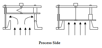
| Figure 5A: Rupture Pin Relief Device End of Pipe with Atmospheric Discharge |
 |
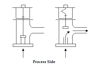
| Figure 5B: Rupture Pin Relief Device Discharge to Header |
There are other options to consider for non-closing relief devices other than rupture disks. Although details are beyond the scope of this article, there is one particular device I wish to bring to your attention and which is gaining in popularity, the Rupture Pin6, 7. Although ASME will not allow what is called a Breaking Pin device to be used as a primary relief device, as of May 1990, it will allow the use of the Rupture Pin device. The two are similar but for the Breaking Pin device to work, the pin must completely break but for the Rupture Pin device to work, the pin only needs to bend or buckle. Another name for this device is the Buckling Pin. Figures 5A and 5B show two types of rupture pin devices. Device "A" might be used directly on a vessel and will relieve to atmosphere. Device "B" might relieve into a piping header.
The rupture pin device usually consists of a piston or plunger on a seat, kept in position by a slender, usually cylindrical pin. At set point, axial forces caused by system pressure acting on the piston or plunger area causes the pin to buckle. The unrestrained pin length, the pin diameter and the modulus of elasticity of the pin material determine the buckling point of the pin.
There is virtually no device size limitation. They have been manufactured as small as 1/8" and as large as 48". There are virtually no pressure or vacuum limits either. They can be designed for a set pressure as low as 2" of water to as high as 35,000 psi and vacuums to as low as 1 psi. Unlike rupture disks, which are solely differential devices, the rupture pin can be designed to sense system pressure only, or differential pressure.
You are now ready to sit through one of those manufacturer's presentations and hopefully understand what he is talking about!
Summary
- API RP520 provides a specification sheet that can be adapted by any company as a standard
- Not all of the information asked for in the API specification sheet is actually required by the manufacturer in order to design the correct rupture disk. This information can be broken down into "must haves", "should haves" and "what is needed to size the disk".
- The manufacturer will always be provided with the "must haves".
- The manufacturer should also be given the "should haves" as this is a way to utilize them as a second pair of eyes and for a consistency check of the sizing.
- There are many different types of rupture disks on the market. Before selecting the correct rupture disk for your particular application, always discuss this with the manufacturer.
- Liquid service has its own set of potential problems for rupture disk design. It is highly recommended that you discuss liquid service with your manufacturer.
- There are other "non-closing" relief devices that can be considered for use. Some can only be used as secondary relief devices. However the one that can be used as a primary relief device and is gaining in popularity is the Rupture Pin.
References
- APIÂ (www.api.org) Recommended Practice 520, "Sizing, Selection, and Installation of Pressure-Relieving Device in Refineries, Part 1-Sizing and Selection", 7th Edition (January 2000)
- API (www.api.org) Recommended Practice 521, "Guide for Pressure-Relieving and Depressuring Systems", 4th Edition (March 1997)
- ASME (www.asme.org) "Boiler and Pressure Vessel Code, Section VIII, Division 1" (1998)
- Continental Disc Corporation (www.contdisc.com), ASME Combination Capacity Factors, Catalogue 1-1111
- Fike (www.fike.com), Technical Bulletin TB8103, July 1999
- www.burstpressuresystems.com
- www.rupturepin.com

 FB
FB

0 Comments