Chemical and Process Engineering Resources

Specify the packing type and column dimensions for a column that will be used to remove chlorine from a gas stream using an organic solvent. Assume the separation requires 20 theoretical stages. The vapor flow is 7000 kg/h, the average vapor density is 4.8 kg/m3. The liquid flow is 5000 kg/h, the average liquid density is 833 kg/m3. The liquid's kinematic viscosity is 0.48 centistokes (4.8 x 10⁻⁷ m2/s)
Step 1: Selecting the Type and Size Packing
This is where the art of designing packed columns begins. Some people believe that there are stringent rules surrounding the choice between random and structured packing. You can think of random packing as the type that comes in a sack and it is simply dumped into the column. Structured packing may come in bales or intricate designs that are stacked in specific patterns. This is probably one of those areas of engineering where past experience in the application is the best guide. Two "areas of choice" where structured packing is used are in very low pressure drop applications and for increasing the capacity of an existing column. Since we're considering a new design with no serious pressure drop constraint, we'll choose the more economical random packing.
Table 1 shows both English and Metric unit packing factors for some common packings.
Generally, the column diameter to packing size ratio should be greater than 30 for Raschig rings, 15 for ceramic saddles, and 10 for rings or plastic saddles. The geometry of your packing will typically be a function of the needed surface area and/or allowable pressure drop. If several packings meet your requirements, you'll typically choose the least expensive so long as it has an acceptable operating life. For our example, we'll choose Pall rings (plastic). For columns over 24 inches in diameter, No. 2 or 2 inch packing should be examined first. By looking at our flowrates, the chances of our column having a diameter of at least 24 inches are good, but we'll verify this later. For now, we'll settle on 2 inch plastic Pall rings for our initial analysis.
Step 2: Determine the Column Diameter
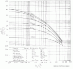
Most methods for determining the size of randomly packed towers are derived from the Sherwood correlation. A design gas rate, G, can be determined with the help of the figure below which is based on correlation from the Sherwood equation.
Each line on the graph is marked with an acceptable pressure drop in inches of water per foot of packing (numbers in parentheses are in mm of water per meter of packing).
 |
| Figure 4: Design Gas Rate Chart |
Guidelines are as follows:
Moderate to high pressure distillation = 0.4 to 0.75 in water / ft packing
= 32 to 63 mm water / m packingVacuum Distillation = 0.1 to 0.2 in water / ft packing
= 8 to 16 mm water / m packingAbsorbers and Strippers = 0.2 to 0.6 in water / ft packing
= 16 to 48 mm water / m packing
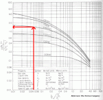
These guidelines are designed around "flooding pressure drops" documented in literature. In other words, for most cases, designing with these pressure drops should help you avoid flooding. In the later stages of design, you may want to perform a thorough flooding calculation. Perry's Chemical Engineers' Handbook covers this topic well. Since we are designing an absorber, we will design for 42 mm water / m packing (you could design for a lower pressure drop, but the column will increase in diameter and most likely cost). First, we'll evaluate the x-axis of the graph above:
 |
| Figure 5: Reading the Design Gas Rate Chart |
(L/V)(vapor density/liquid density)0.5 = (5000/7000)(4.2/833)0.5 = 0.0507
Note that 4.2 kg/m3 was used for the vapor density. The average vapor density was given as 4.8 kg/m3. However, at the top of the column, the vapor will be less dense and at it's highest velocity. This is what you should design for. As a rule of thumb, I reduce the average vapor density by about 15% for design, however if you can get real data from a similar tower, certainly do so! Reading the intersection of the 42 mm water/m packing line and 0.05 on the axis, we find a value of 1.5 for the y-axis (see Figure 5).
From the previous charts, we read a packing factor of 24 for 2 inch plastic Pall rings. All other information is know so we can solve for G as shown on the y-axis of the graph:
G = [1.5 [(4.2)(833-4.2)]/[(10.764)(24)(0.48)0.1]]0.5 = 4.66 kg/m2 s
Now, we solve for the column cross sectional area:
Ax = Vapor Flow / G = 7000 kg/h / [(4.66 kg/m2 s)(3600 s/hour)] = 0.42 m2
and the column diameter is calculated by:
Diameter = [Ax / (PI/4)]0.5 = [0.42/(PI/4)]0.5 = 0.73 m or 2.4 ft
So our assumption of at least a 24 in column diameter is accurate. If it had not been accurate, G would be recalculated using a smaller packing which would also correspond to a larger packing factor.
Step 3: Determine the Column Height
Perhaps the most interesting step in designing a packed column is deciding how tall to build it. You should first ask yourself "What stage of the design are we currently working on?" If the design is preliminary, the general HETP (Height Equivalent to a Theoretical Plate) will work well. If the design requires a higher degree of accuracy, I recommend consulting the packing manufacturer or a book entitled Distillation Design by Henry Kister (McGraw-Hill, ISBN 0-07-034909-6). Distillation Design contains an exhaustive list of HETP values based on the components of the system and the type of packing used (Chapters 10 and 11). As for preliminary estimates, the following HETP values should be used:
| Setup | HETP ft (m) | |
| Method | Packing Size (in) | |
| Distillation | 1.0 | 1.5 (0.46) |
| 1.5 | 2.2 (0.67) | |
| 2.0 | 3.0 (0.91) | |
| Vacuum Distllation | 1.0 | 2.0 (0.67) |
| 1.5 | 2.7 (0.82) | |
| 2.0 | 3.5 (1.06) | |
| Absorption / Stripping | All Sizes | 6.0 (1.83) |
To determine the height of the absorption tower in our example, we multiple the 20 theoretical stages by 6 ft or 1.83 m. We estimate the height of the tower to be 120 ft or about 37 meters.
Other Notes
While our example problem focused on absorption, packed towers are also widely used in distillation. Perhaps the most popular of which is the well documented vacuum distillation of ethylbenzene and styrene in the production of styrene. Distillation Design covers this application very well.

 FB
FB


5 Comments
HAI , ANY BODY EXPLANIED ME FOR CRYOGENCIC PROCESS.
Very well explained
How to calculate number of stages in a packed absorption column.....?
if a had high flow rate of gas. i wanna absorb CO2 in MEA 30 % solution flow rate of CO2 is 9kg/s and for that flow rate MEA flow rate is 16.73 kg/s to absorb 98% CO2.Should i design packed or tray column