 FB
FBChemical and Process Engineering Resources
Design Considerations for Shell and Tube Heat Exchangers
Nov 08 2010 01:30 PM | Chris Haslego

When preparing to design a heat exchanger, do you ever wonder where to start? You've done it before, but you hate that feeling of getting half way through the design and realizing that you forgot to consider one important element.
The thought process involved is just as important as the calculations involved. Let's try to map out a heat exchanger design strategy. We'll do so with a series of questions followed by information to help you answer the questions.
The thought process involved is just as important as the calculations involved. Let's try to map out a heat exchanger design strategy. We'll do so with a series of questions followed by information to help you answer the questions.
"Zones" can best be defined as regimes of phase changes where the overall heat transfer coefficient (Uo) will vary. Using T-Q (Temperature-Heat) diagrams are the best way to pinpoint zones. The system is defined as co-current or countercurrent and the diagram is constructed. The diagram on the left illustrates the use of T-Q diagrams. These diagrams should accompany your basic (input-output) diagram of the heat exchanger. Chemical #1 enters the shell at 200 °C as a superheated vapor. In Zone 1, it releases heat to the tubeside chemical (Chemical #2). Zone 1 ends just a Chemical #1 begins to condense. The tubeside (Chemical #2) enters as a liquid or gas and does not change phase throughout the exchanger. Chemical #1 leaves Zone 1 and enters Zone 2 at its boiling temperature, Tb1. T* marks the temperature of Chemical #2 when Chemical #1 begins to condense. In Zone 2, Chemical #1 condenses to completion while Chemical #2 continues to increase in temperature. The temperature of Chemical #2 when Chemical #1 is fully condensed is denoted at T**. Finally, in Zone 3, both chemicals are liquids. Chemical #1 is simply liberating heat to Chemical #2 as it becomes a subcooled liquid and exits the shell at 100 °C.
Defining zones is one of the most important aspects of heat exchanger design. It is also important to remember that if your process simulator does not support zoned analysis (such as Chemcad III), you should model each zone with a separate heat exchanger. Thus, the previous illustration would require 3 heat exchangers in the simulation. BUT, do not draw 3 exchangers on your PFD (Process Flow Diagram). This is all happening in one exchanger.
This information is critical in establishing the mass and energy balance around the exchanger. Operating pressures are particularly important for gases as their physical properties vary greatly with pressure.
If you're using a process simulator, obtaining the physical properties of your streams should be just a click of the mouse away. However, if performing the calculation by hand, you may have to do some estimating as the streams may not be of pure substances. Also, you should get the physical properties for each zone separately to ensure accuracy, but in some cases it is acceptable to use an average value. This would be true of Chemical #2 in the tubes since it is not changing phase or undergoing a truly significant temperature change (over 100 °C). Physical properties that you will want to collect for each phase of each stream will include: heat capacity, viscosity, thermal conductivity, density, and latent heat (for phase changes). These are in addition to the boiling points of the streams at their respective pressures.
Pressure drops are very important in exchanger design (especially for gases). As the pressure drops, so does viscosity and the fluids ability to transfer heat. Therefore, the pressure drop and velocities must be limited. The velocity is directly proportional to the heat transfer coefficient which is motivation to keep it high, while erosion and material limits are motivation to keep the velocity low. Typical liquid velocities are 1-3 m/s (3-10 ft/s). Typical gas velocities are 15-30 m/s (50-100 ft/s). Typical pressure drops are 30-60 kPa (5-8 psi) on the tubeside and 20-30 kPa (3-5 psi) on the shellside.
This can be answered by a simple energy balance from one of the streams.
Unfortunately, this is where the real fun begins in heat exchanger design! You'll need to find estimates for the heat transfer coefficients for your system. These can be found in most textbooks dedicated to the subject or in "Perry's Chemical Engineers' Handbook". Once you've estimated the overall heat transfer coefficient, use the equation Q=Uo x A x LMTD ("LMTD" is short for Log Mean Temperature Difference) to get your preliminary area estimate. Remember to use the above equation to get an area for each zone, then add them together.
Now that you have an area estimate, it's time to find a geometry that meets your needs. Once you've selected a shell diameter, tubesheet layout, baffle and tube spacing, etc., it's time to check your velocity and pressure drop requirements to see if they're being met. Experienced designers will usually combine these steps and actually obtain a tube size that meets the velocity and pressure drop requirements and then proceed. Some guidelines may be as follows: 3/4 in. and 1.0 in. diameter tubes are the most popular and smaller sizes should only be used for exchangers needing less than 30 m2 of area. If your pressure drop requirements are low, avoid using four or more tube passes as this will drastically increase your pressure drop. Once you have a geometry selected that meets all of your needs, it's on to the next step.
This is where you'll spend much of your time in designing a heat exchanger. Although many textbooks show Nu=0.027(NRE)0.8(NPR)0.33 as the "fundamental equation for turbulent flow heat transfer", what they sometimes fail to tell you is that the exponents can vary widely for different situations. For example, condensation in the shell has different exponents than condensation in the tubes. Use this fundamental equation if you must, but you should consult a good resource for accurate equations. I highly recommend the following: "Handbook of Chemical Engineering Calculations", 2nd Ed., by Nicholas P. Chopey from McGraw-Hill publishers (ISBN 0070110212). Also, don't forget to include the transfer coefficient across the tube wall and the fouling coefficient. These can be very significant!
If you recall, you used estimated heat transfer coefficients to get an initial area. Now it's time to recalculate the area.
Now you're on your way, pick a new geometry corresponding to your new ("actual") area, check the velocity and pressure drop, calculate the overall heat transfer coefficient again. How does it compare with the previously calculated value? If it is not within 5-10%, recalculate the process over and over (using your new value for Uo) until it does! Sounds like alot of work. Add in the fact that some of the individual heat transfer coefficients require iterative solutions and it's not hard to see why people usually use a complex spreadsheet or a program to do this. You can save some time by using estimates that you've undoubtedly seen, however you must realize that each time you estimate, you're losing accuracy.
Remember two main items:
The thought process involved is just as important as the calculations involved. Let's try to map out a heat exchanger design strategy. We'll do so with a series of questions followed by information to help you answer the questions.
Asking the Right Questions
Is there a phase change involved?
The thought process involved is just as important as the calculations involved. Let's try to map out a heat exchanger design strategy. We'll do so with a series of questions followed by information to help you answer the questions.
How many zones are there in my system?
"Zones" can best be defined as regimes of phase changes where the overall heat transfer coefficient (Uo) will vary. Using T-Q (Temperature-Heat) diagrams are the best way to pinpoint zones. The system is defined as co-current or countercurrent and the diagram is constructed. The diagram on the left illustrates the use of T-Q diagrams. These diagrams should accompany your basic (input-output) diagram of the heat exchanger. Chemical #1 enters the shell at 200 °C as a superheated vapor. In Zone 1, it releases heat to the tubeside chemical (Chemical #2). Zone 1 ends just a Chemical #1 begins to condense. The tubeside (Chemical #2) enters as a liquid or gas and does not change phase throughout the exchanger. Chemical #1 leaves Zone 1 and enters Zone 2 at its boiling temperature, Tb1. T* marks the temperature of Chemical #2 when Chemical #1 begins to condense. In Zone 2, Chemical #1 condenses to completion while Chemical #2 continues to increase in temperature. The temperature of Chemical #2 when Chemical #1 is fully condensed is denoted at T**. Finally, in Zone 3, both chemicals are liquids. Chemical #1 is simply liberating heat to Chemical #2 as it becomes a subcooled liquid and exits the shell at 100 °C.
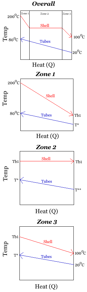 |
| Figure 1: Zones Analysis |
Defining zones is one of the most important aspects of heat exchanger design. It is also important to remember that if your process simulator does not support zoned analysis (such as Chemcad III), you should model each zone with a separate heat exchanger. Thus, the previous illustration would require 3 heat exchangers in the simulation. BUT, do not draw 3 exchangers on your PFD (Process Flow Diagram). This is all happening in one exchanger.
What are the flowrates and operating pressures involved in my system?
This information is critical in establishing the mass and energy balance around the exchanger. Operating pressures are particularly important for gases as their physical properties vary greatly with pressure.
What are the physical properties of the streams involved?
If you're using a process simulator, obtaining the physical properties of your streams should be just a click of the mouse away. However, if performing the calculation by hand, you may have to do some estimating as the streams may not be of pure substances. Also, you should get the physical properties for each zone separately to ensure accuracy, but in some cases it is acceptable to use an average value. This would be true of Chemical #2 in the tubes since it is not changing phase or undergoing a truly significant temperature change (over 100 °C). Physical properties that you will want to collect for each phase of each stream will include: heat capacity, viscosity, thermal conductivity, density, and latent heat (for phase changes). These are in addition to the boiling points of the streams at their respective pressures.
What are the allowable pressure drops and velocities in the exchanger?
Pressure drops are very important in exchanger design (especially for gases). As the pressure drops, so does viscosity and the fluids ability to transfer heat. Therefore, the pressure drop and velocities must be limited. The velocity is directly proportional to the heat transfer coefficient which is motivation to keep it high, while erosion and material limits are motivation to keep the velocity low. Typical liquid velocities are 1-3 m/s (3-10 ft/s). Typical gas velocities are 15-30 m/s (50-100 ft/s). Typical pressure drops are 30-60 kPa (5-8 psi) on the tubeside and 20-30 kPa (3-5 psi) on the shellside.
What is the heat duty of the system?
This can be answered by a simple energy balance from one of the streams.
What is the estimated area of the exchanger?
Unfortunately, this is where the real fun begins in heat exchanger design! You'll need to find estimates for the heat transfer coefficients for your system. These can be found in most textbooks dedicated to the subject or in "Perry's Chemical Engineers' Handbook". Once you've estimated the overall heat transfer coefficient, use the equation Q=Uo x A x LMTD ("LMTD" is short for Log Mean Temperature Difference) to get your preliminary area estimate. Remember to use the above equation to get an area for each zone, then add them together.
What geometric configuration is right for my exchanger?
Now that you have an area estimate, it's time to find a geometry that meets your needs. Once you've selected a shell diameter, tubesheet layout, baffle and tube spacing, etc., it's time to check your velocity and pressure drop requirements to see if they're being met. Experienced designers will usually combine these steps and actually obtain a tube size that meets the velocity and pressure drop requirements and then proceed. Some guidelines may be as follows: 3/4 in. and 1.0 in. diameter tubes are the most popular and smaller sizes should only be used for exchangers needing less than 30 m2 of area. If your pressure drop requirements are low, avoid using four or more tube passes as this will drastically increase your pressure drop. Once you have a geometry selected that meets all of your needs, it's on to the next step.
Now that I have a geometry in mind, what is the actual overall heat transfer coefficient?
This is where you'll spend much of your time in designing a heat exchanger. Although many textbooks show Nu=0.027(NRE)0.8(NPR)0.33 as the "fundamental equation for turbulent flow heat transfer", what they sometimes fail to tell you is that the exponents can vary widely for different situations. For example, condensation in the shell has different exponents than condensation in the tubes. Use this fundamental equation if you must, but you should consult a good resource for accurate equations. I highly recommend the following: "Handbook of Chemical Engineering Calculations", 2nd Ed., by Nicholas P. Chopey from McGraw-Hill publishers (ISBN 0070110212). Also, don't forget to include the transfer coefficient across the tube wall and the fouling coefficient. These can be very significant!
What is the actual area of the exchanger using the 'actual' heat transfer coefficient?
If you recall, you used estimated heat transfer coefficients to get an initial area. Now it's time to recalculate the area.
Enter the Calculation Loop
Now you're on your way, pick a new geometry corresponding to your new ("actual") area, check the velocity and pressure drop, calculate the overall heat transfer coefficient again. How does it compare with the previously calculated value? If it is not within 5-10%, recalculate the process over and over (using your new value for Uo) until it does! Sounds like alot of work. Add in the fact that some of the individual heat transfer coefficients require iterative solutions and it's not hard to see why people usually use a complex spreadsheet or a program to do this. You can save some time by using estimates that you've undoubtedly seen, however you must realize that each time you estimate, you're losing accuracy.
Remember two main items:
- ZONED ANALYSIS
- ACCURACY OF INITIAL OVERALL HEAT TRANSFER COEFFICIENT
3 Comments
Good day to you. this is very good explanation for Heat exchanger. can this calculation be used tor water Bath Heater
This procedure is for continuous, once through service. A bath heater would be a batch heating service that would require different treatment in the calculation.
NITRIC ACID PRODUCTION PLANT:-
(Upstream of Waste heat boiler)Economizer design data are as mentioned below:-
SHELL - design pressure 34 bar - Boiler feed water service - MOC SS304
TUBE - design pressure 8.27 bar - NOx gases - MOC SS321
During boiler testing/inspection (i.e. IBR) at high pressure i.e at 51 bar (1.5 * 34) my economizer tubes got bursted.
Please explain reason if anyone could??
1) Is it due to shell side having high pressure and tube side having low pressure - if that's the reason is it design mistake and if it's not the reason than how tube can sustain this much pressure from external forces.?