Chemical and Process Engineering Resources

Hydrocracking
The need for gasoline of a higher quality than that obtained by catalytic cracking led to the development of the hydrocracking process. The history of the process goes back to the later 1920s when a plant for the commercial hydrogenation of brown coal was commissioned at Leuna in Germany. Tungsten sulphide was used as a catalyst in this one-stage unit , in which high reaction pressures, 200-300 bar, were applied. The catalyst displayed a very high hydrogenation activity: the aromatic feedstock, coal and heavy fractions of oil, containing sulphur, nitrogen and oxygen, was virtually completely converted into paraffins and isoparaffins. The result of the Leuna plant - loss of octane number from aromatic hydrogenation of impurities in the feedstock, notably nitrogen compounds, followed by a hydrocracking step. In 1939, ICI developed the second-stage catalyst for a plant that contributed largely to Britain''s supply of aviation gasoline in the subsequent years.
During World War II, two stage processes were applied on a limited scale in Germany, Britain and USA. In Britain, feedstock were creosote from coal tar and gas oil from petroleum. In the USA, Standard Oil of New Jersey operated a plant at Baton Rouge, producing gasoline from a Venezuelan kerosine/light gasoil fraction. Operating conditions in those units were comparable: approximate reaction temperature 400 0C and reaction pressures of 200-300 bar.
After the war, commercial hydrocracking was stopped because the process was too expensive. Hydocracking research, however, continued intensively. By the end of the 1950s, the process had become economic, for which a number of reasons are identified.
The development of improved catalyst made it possible to operate the process at considerably lower pressure, about 70-150 bar.Â
This in turn resulted in a reduction in equipment wall thickness, whereas simultaneously, advances were made in mechanical engineering, especially in the field of reactor design and heat transfer. These factors, together with the availability of relatively low cost hydrogen from steam reforming process, brought hydrocracking back on the refinery scene. The first units of the second generation were built in USA to meet the demand for conversion of surplus fuel oil in the gasoline-oriented refineries.
Now, hdyrocracking is a well established process from many licensors.
Basis for the Choice of Conversion Routes
Refiners are continuously faced with trends towards increased conversion, better product qualities and more rapidly changing product patterns. Various processes are available that can meet the requirements to a greater or lesser degree: coking, visbreaking/thermal cracking, catalytic cracking and hydrocracking.
 |
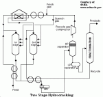
| Figure 6: Typical Hydrocracking Process |
The type of process applied and the complexity of refineries in various parts of the world are determined to a greater extent by the product distribution required. As a consequence, the relatively importance of the above process in traditionally fuel-oil dominated refineries such as those in Western Europe will be quite different from those of gasoline-oriented refineries in, for instance, the USA.
An important aspect of the coking, thermal cracking and catalytic cracking process is that they operate at low pressures. This gives advantages in the fields of capital, matallurgy and engineering.
A particular feature of the hydrocracking process, as compared with its alternatives, is its flexibility with respect to product outturn and high quality of its products. In the areas where quantitative imbalance exists of lighter products, middle distillates and fuel, hydrocracking is a most suitable process for correction. Moreover, the hydrocracker does not yield any coke or pitch byproduct: the entire feedstock is converted into the required product range, an important consideration in a situation of limited crude oil availability. The development of the low-pressure catalytic reforming process, which produces relatively cheap, high quality hydrogen, has continued substantially to the economic viability of hydrocracking. On the whole, hydrocracking can handle a wider range of feedstock than catalytic cracking, although the latter process has seen some recent catalyst developments which narrowed the gap. There are also examples where hydrocracking is complementary rather than alternative to the other conversion process; an example, cycle oils, which cannot be recycled to extinction in the catalytic cracker, can be processed in the hydrocracker.
Notwithstanding many extensive comparisons between the various processes, the experince shows the generalisation with respect to the optimum conversion route still cannot be made.
Process Description
All hydrocracking process are characterised by the fact that in a catalytic operation under relatively high hydrogen pressure a heavy oil fraction is treated to give products of lower molecular weight.
Hydrocracking covers widely different fuels, ranging from C3/C4 production from naphta, on the other hand, to luboil manufacture from deasphalted oils, on the other.
Most hydrocrackers use fixed beds of catalyst with downflow of reactants. The H-Oil process developed by Hydrocarbon Research Corp and Cities Service R & D employs an ebullient bed reactor in which the beds of particulate catalyst are maintained in an ebullient or fluidised condition in upflowing reactants.
When the processing severity in a hydrocracker is increased, the first reaction occuring leads to saturation of any olefinic material present in feedstock. Next comes the reaction of desulphurisation, denitrogenation and de-oxygenation. These reactions constitute treating steps during which in most cases, only limited cracking takes place. When the severity is increased further, hydrocracking reaction is initiated. They proceed at various rates, with the formation of intermediate products (eg. saturation of aromatics), which are subsequently cracked into lighter products.
Process Configuration
When the treating step is combined with the cracking reaction to occur in one reactor, the process is called a SINGLE-STAGE PROCESS.
SINGLE-STAGE PROCESS: In this simplest of the hydrocracker configuration, the lay out of the reactor section generally resembles that of hydrotreating unit. This configuration will find application in cases where only moderate degree of conversion (say 60% or less) is required. It may also be considered if full conversion, but with a limited reduction in molecular weight, is aimed at. An example is the production of middle distillates from heavy distillate oils. The catalyst used in a single-stage process comprises a hydrogenation function in combination with a strong cracking function. The hydogenation function is provided by sulphided metals such as cobalt, molybdenum and nickel. An acidic support, usually alumina, attends to the cracking function. Nitrogen compounds and ammonia produced by hydrogenation interfere with acidic activity of the catalyst. In the cases of high/full conversion is required, the reaction temperatures and run lenghts of interest in commercial operation can no longer be adhered to. It becomes necessary to switch to a multi-stage process, in which the cracking reaction mainly takes place in an added reactor. With regard to the adverse effect of ammonia and nitrogen compounds on catalyst activity, two versions of the multi stage hydrocracker have been developed: the TWO STAGE HYDROCRACKER and SERIES FLOW HYDROCRACKER.
In the first type, the undesirable compounds are removed from the unconverted hydrocarbons before the latter are charged to the cracking reactor. This type is called the TWO STAGE PROCESS. The other variety is ofen referred to as SERIES FLOW HYDROCRACKER. This type uses a catalyst with an increased tolerance towards nitrogen, both as ammonia and in organic form.
TWO STAGE CONFIGURATION: Fresh feed is preheated by heat exchange with effluent from the first reactor. It is combined with part of a not fresh gasecycle gas mixture and passes through a first reactor for desulphurisation/denitrogenation step. These reactions, as well as those of hydrocracking, which occurs to a limited extent in the first reactor, are exothermic. The catalyst inventory is therefore divided among a number of fixed beds. Reaction temperatures are controlled by introducing part of the recycle gas as a quench medium between beds. The ensuing liquid is fractionated to remove the product made in the first reactor. Unconverted, material, with a low nitrogen content and free of ammonia, is taken as a bottom stream from the fractionation section. After, heat exchange with reactor effluent and mixing with heated recycle gas, it is sent to the second reactor. Here most of the hydrocracking reactions occur. Strongly acidic catalyst with a relatively low hydrogenation activity (metal sulphides on, for example, amorphous silica-alumina) are usually applied. As in the first reactor, the exothermicity of the process is controlled by using recycle gas as quench medium the catalyst beds. Effluent from the second reactor is cooled and joins first stage effluent for separation from recycle gas and fractionation. The part of the second reactor feed that has remained unconverted is recycled to the reactor. Feedstock is thereby totally converted to the product boiling range.
SERIES FLOW CONFIGURATION: The principal difference is the elimination of first stage cooling and gas/liquid separation and the interstage ammonia removal step. The effluent from the first stage is mixed with more recycle gas and routed direct to the inlet of the second reactor. In contrast with the amorphous catalyst of the two-stage process, the second reactor in series flow generally has a zeolitic catalyst, based on crystalline silica-alumina. AS in the two stage process, material not converted to the product boiling range is recycled from the fractionation section.
Hydrocracking Conclusions
Both two stage and series flow hydrocracking are flexible process: they may yield, in one mode of operation, only naphtha and lighter products and, in a different mode, only gasoil and lighter products. In the naphtha mode, both configurations have comparable yield patterns. In modes for heavier products, kerosine and gasoil, the two stage process is more selective because product made in the first reactor is removed from the second reactor feed, In series flow operation this product is partly overcracked into lighter products in the second reactor.

 FB
FB

7 Comments
Thank u Sir !
Great article to understand the functions of whole refinery, !!