Chemical and Process Engineering Resources

Step #4: Preliminary valve selection
Don't make the mistake of trying to match a valve with your calculated Cv value. The Cv value should be used as a guide in the valve selection, not a hard and fast rule. Some other considerations are:
a. Never use a valve that is less than half the pipe size
b. Avoid using the lower 10% and upper 20% of the valve stroke. The valve is much easier to control in the 10-80% stroke range.
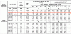
Before a valve can be selected, you have to decide what type of valve will be used (See the list of valve types later in this article). For our case, we'll assume we're using an equal percentage, globe valve (equal percentage will be explained later). The valve chart for this type of valve is shown below. This is a typical chart that will be supplied by the manufacturer (as a matter of fact, it was!)

For our case, it appears the 2 inch valve will work well for our Cv value at about 80-85% of the stroke range. Notice that we're not trying to squeeze our Cv into the 1 1/2 valve which would need to be at 100% stroke to handle our maximum flow. If this valve were used, two consequences would be experienced: the pressure drop would be a little higher than 15 psi at our design (max) flow and the valve would be difficult to control at maximum flow. Also, there would be no room for error with this valve, but the valve we've chosen will allow for flow surges beyond the 150 gpm range with severe headaches!
So we've selected a valve...but are we ready to order? Not yet, there are still some characteristics to consider.
Step #5: Check the Cv and stroke percentage at the minimum flow
If the stroke percentage falls below 10% at our minimum flow, a smaller valve may have to be used in some cases. Judgements plays role in many cases. For example, is your system more likely to operate closer to the maximum flowrates more often than the minimum flowrates? Or is it more likely to operate near the minimum flowrate for extended periods of time. It's difficult to find the perfect valve, but you should find one that operates well most of the time. Let's check the valve we've selected for our system:
Referring back to our valve chart, we see that a Cv of 6.5 would correspond to a stroke percentage of around 35-40% which is certainly acceptable. Notice that we used the maximum pressure drop of 15 psi once again in our calculation. Although the pressure drop across the valve will be lower at smaller flowrates, using the maximum value gives us a "worst case" scenario. If our Cv at the minimum flow would have been around 1.5, there would not really be a problem because the valve has a Cv of 1.66 at 10% stroke and since we use the maximum pressure drop, our estimate is conservative. Essentially, at lower pressure drops, Cv would only increase which in this case would be advantageous.
Step #6: Check the gain across applicable flowrates
Gain is defined as:
Now, at our three flowrates:
Qmin = 25 gpm
Qop = 110 gpm
Qdes = 150 gpm
we have corresponding Cv values of 6.5, 28, and 39. The corresponding stroke percentages are 35%, 73%, and 85% respectively. Now we construct the following table:
| Flow (gpm) | Stroke (%) | Change in flow (gpm) | Change in Stroke (%) |
| 25 | 35 | 110-25 = 85 | 73-35 = 38 |
| 110 | 73 | ||
| 150 | 85 | 150-110 = 40 | 85-73 = 12 |
Gain #1 = 85/38 = 2.2
Gain #2 = 40/12 = 3.3
The difference between these values should be less than 50% of the higher value.
0.5 (3.3) = 1.65 and 3.3 - 2.2 = 1.10. Since 1.10 is less than 1.65, there should be no problem in controlling the valve. Also note that the gain should never be less than 0.50. So for our case, I believe our selected valve will do nicely!
Other Notes
Another valve characteristic that can be examined is called the choked flow. The relation uses the FL value found on the valve chart. I recommend checking the choked flow for vastly different maximum and minimum flowrates. For example if the difference between the maximum and minimum flows is above 90% of the maximum flow, you may want to check the choked flow. Usually, the rule of thumb for determining the maximum pressure drop across the valve also helps to avoid choking flow.

 FB
FB


16 Comments
Hi, Chris
I'm Emad Elgebesy. Senior process engineer in Worley Parsons. First of all, thanks for your clear efforts on the community, And im willing to share my experiance in this regard.
In Worley Parsons, we did the valve calculation for, single phase & two phase. The above mentioned calculation did not demonstrate which phase is, But i think this liquid phase valve calculation only.
After calculating the Cv, Supplier should verify the strock range (10% to 90%) is commnly used, noise level& body size as well.
Finally, there is many free control valve software of FirstVue do regirous calculation
Regards
Emad
thanks for the info Chris
Dear Chris,
If the vendor did not supply the valve chart, is there any we can get the control valve opening by using calculated Cv and rated Cv?
Cv charts are generally made for experimental data. If your valve supplier doesn't have a Cv chart for a valve that they sold to you...find a new valve supplier...that is not acceptable.
Chris,
Nice article!
I'd like to make a suggestion for a follow-up article. There are many times that we size liquid control valves in systems where the source pressure comes from a gas in the system instead of a pump (I am thinking of scrubber dump valves). In these situations, after sizing the liquid valve, we often need to determine the "gas blowby" rate, which is how much gas would flow through the valve if the liquid level control loop failed and left the valve wide open. This is often required when sizing pressure safety valves further downstream in the system. It would be great to add an additional step to this article to calculate the maximum gas flow through the selected liquid control valve.
Regards,
Paul
Great job
Thanks Chris
Really Helpful post for someone like me who is recent graduate, explained in very easy way.
I have few questions.
1. is this procedure and equations are useful for compressible fluids/ Gases
2. Do you have anything for selecting control valve for compressible fluids/gases ? (Explaining Nice and easy with thumb rules for selection criteria, like gain should never be less than 0.5 etc.)
I found a handbook from Emerson on control valve. That procedure seems to be too complicated or theoretical.( Too many contents no thumb rules ) Page 118 of Fisher control valve handbook, Emerson (its free on google - couldn't post the link)
Beautiful thanks Chris
Dear all,
In maximum case of flowrate, why the pressure dropcontrol valve should have the minimum limitation?
For example, when calculating hydraulic balance, at max case ( 120% normal flowrate), the pressure drop of control valve for liquid service is from 0.5 to 1 kg/cm2?
In my opinion, if the pressure drop of CV is too small, the Cv of CV will be very big. Therefore, even though the CV is full open at max. case, CV can not control the flowrate is the case, right?