 FB
FBChemical and Process Engineering Resources

Example Problem
Consider the following example:
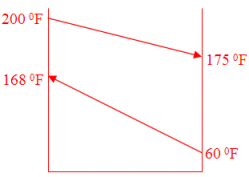 150,000 lb/h of SAE 30 oil is being cooled from 200 °F to 175 °F by 75,000 lb/h of water. The water enters the exchanger at 60 °F and leaves at 168 °F. The average viscosity of the water passing through the unit is 0.33 cP and the average viscosity of the oil in the unit is 215 cP. The maximum allowable pressure drop through the plate heat exchanger is 15 psig on the hot and cold sides.
Step 1: Calculate the LMTD
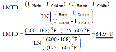 | Eq. (2) |
Step 2: Calculate NTUHOT and NTUCOLD
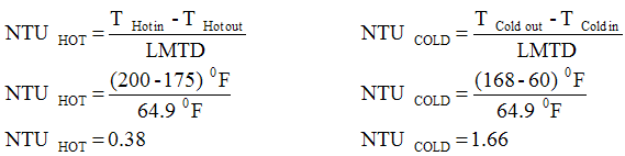 | Eq. (3) |
Step 3: Read hHot from 0.25 < NTU < 2.0 chart for hydrocarbons
Although is there not a viscosity line for 215 cP, the line representing "100 cP" can be or viscosities up to about 400-500 cP. The heat exchanger will be pressure drop limited and the heat transfer coefficient will not change appreciably over this viscosity range for plate and frame exchangers. Reading from the chart, a pressure drop of 15 psig corresponds to hHot @ 50 Btu/h ft2 °F.
Step 4: Read hCold from 0.25 < NTU < 2.0 chart for water based liquids
Again, you will note that the exact viscosity line needed for pure water (0.33 cP) in this case is not available. However, the "1.0 cP" line on the chart will provide a very good estimate of the heat transfer coefficient that pure water will exhibit. Reading from the chart, a pressure drop of 15 psig corresponds to hCold @ 3000 Btu/h ft2 °F.
Step 5: Calculate the Overall Heat Transfer Coefficient (OHTC)
Assume a stainless steel plate with a thickness of 0.50 mm is being used. 316 stainless steel has a thermal conductivity of 8.67 Btu/h ft °F.
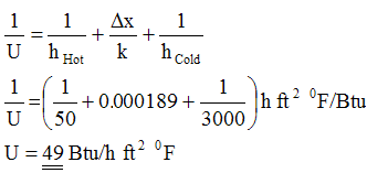 | Eq. (4) |
Another Example
 150,000 lb/h of water is being cooled from 200 °°F by 150,000 lb/h of NaCl brine. The brine enters the exchanger at 50 °F and leaves at 171 °F. The average viscosity of the water passing through the unit is 0.46 cP and the average viscosity of the brine in the unit is 1.10 cP. The maximum allowable pressure drop through the plate heat exchanger is 10 psig on the hot (water) side and 20 psig on the cold (brine) side.
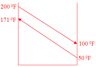
As before, the LMTD is calculated to be 38.5 °F. NTUHot and NTUCold are calculated as 2.59 and 3.14 respectively. Reading hHot and hCold from the chart for 2.0 < NTU < 4.0 (water based), gives about 2000 Btu/h ft2 °F and 2500 Btu/h ft2 °F respectively. Although the material of choice may be Titanium or Palladium stabilized Titanium, we will use the properties for stainless steel for our preliminary sizing. Calculating the OHTC as before yields 918 Btu/h ft2 °F.
5 Comments
my only query is that graphs given here ,can they be used for bloc welded plate heat exchanger designing ?.
Sir,
Very nice article and very helpful.
But my query is that how these graph comes can you
sir please provide some baics about these.
Thanks
Ashish
Hindalco
These are generalized correlations that I put together when I worked for Alfa Laval. They are appropriate for early phase design.
Dear Sir,
My NTUcold is calculated to be 0.09 based on temperature difference of 4 C (37-33)C and LMTD of 40.86C. For this NTU there does not seem to be a graph.
The cooling water temperature limits are fixed here based on cooling tower's profile.