 FB
FBChemical and Process Engineering Resources


 The authors share their experience in debottlenecking a methanol plant at GNFC Ltd. The project involved the commissioning of a state of the art Isothermal reactor from Linde.
GNFC is located at Bharuch, Gujarat  India and is engaged in manufacturing of fertilizers. The key products are urea, ANP, CAN, formic acid, methanol, acetic acid, and nitric acid (weak/strong).  GNFC owns two (2) methanol plants.  A small, old plant called Methanol-I with a capacity of 60 MTD and another Methanol-II plant with a capacity of 300 MTD. Methanol-I was commissioned in 1985. It was designed to operate on the feed gas from the rectisol wash unit of an ammonia plant. With the methanol market improvement in the late 90’s, this plant became an attractive option for a capacity increase. It is now producing more than 180 MTD (three times the design capacity) due to implemented, stepwise modifications in the plant. |
Â
Â
Â
Â
Â
Â
Â
Â
Â
Brief History - Enhancing the Methanol-I Plant Capacity
Originally, this plant was designed to operate on feed gas from an ammonia plant consisting of a gas mixture of 75% hydrogen, 22% carbon dioxide, 1% carbon monoxide and some inerts. Â The reaction of the methanol in gas rich in CO2 is milder as it produces water along with methanol. Â The crude methanol concentration is also lower. Water further retards the rate of reaction. The two reactions involved here are:
H2 + CO2 ---->   CH3OH + H2O        +          9.8 kcal/kgmol           Â
H2 + CO   ---->  CH3OH                   +        21.6 kcal/kgmol                     Â
Normally, a gas mixture of H2 + CO + CO2 is used in a proportion measured in terms of a “R†value (H2-CO2)/(CO+CO2) equal to 2.0 to get an optimum methanol conversion per pass.
| Authors: CD Bhakta – Chief Manager (Projects) at GNFC Ltd. Send inquiries to: aishaikh"at symbol"gnvfc.com |
Changes to the process included:
- A methanol chiller was introduced in the gas cooling circuit at the reactor outlet to reduce the methanol concentration and temperature in the recycle gas which helped to increase the methanol production from 4~5 MTD up to 75 MTD level.
- Setting up a synthesis gas generation unit (SGGU) to supply CO rich gas from natural gas reformer in February 1998.  This gas composition is better for methanol production compared to the rectisol wash gas which is rich in CO2. The synthesis gas and distillation loops were debottlenecked by replacing of some control valves, installation of exchangers, and other modifications. The capacity was boosted to 100 to 120 MTD.
- Replacement of the refining column trays with high capacity Superfrac™ trays from Kostch Glistch India Ltd in October 2002. This, along with other peripheral modifications, were made to increase distillation capacity to 145 MTD.
- Replacement of the quench adiabatic methanol convertor to Linde’s Isothermal Reactor and debottlenecking of the distillation loops for higher capacity.  The capacity of the plant was increased to 160 MTD in September 2003. Â
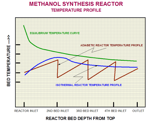
Major advantages of Isothermal Reactor include:Â
Lower pressure drop in reactor
Less temperature variation
Increased life of catalyst
Narrow band of temperature differences in the reactor catalyst bed
Sustained Production Level throughout the catalyst life due to better conversion
Less by-product formation
Effective heat recovery
Figure 1 below shows the temperature profile in the isothermal reactor. Â
Compared to the expected 160 MTD production capacity, the unit has achieved a stable production level of 185~190 MTD.
A flow diagram of the new loop is shown in Figure 2 below.  In this article, we’ll focus on this latest dimension added to the plant, highlighting the re-commissioning experiences.Â
 | Â | 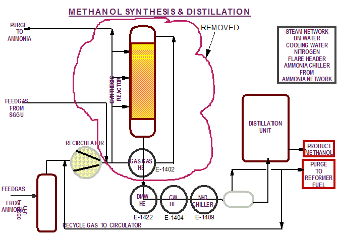 | Â | 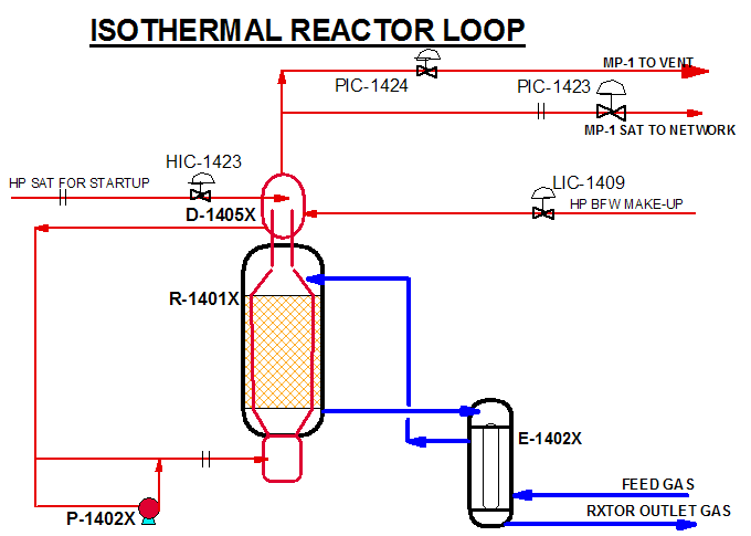 |
| Figure 1: Comparing Reactor Temperature Profiles Before and After the Changes | Â | Figure 2: Changes in the Methanol Synthesis and Distillation Loops | Â | Figure 3:Â Methanol Synthesis and Distillation Loops After Changes |
1 Comments
Thank You Sir !