Chemical and Process Engineering Resources
Reactor Catalyst Charging
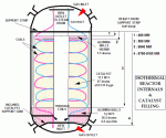
This was the first reactor of its kind at GNFC with spiral wound coils within the shell. The catalyst is to be charged on the shell side, while the cooling medium (boiler feed water) flows in the tubes via thermosiphon.  During the startup, the boiler feed water circulation pump maintains the water circulation.
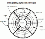
As shown in Figures 4 and 5, the reactor coils are supported at both the ends by six support strips moving radially outward from the central mandrill. This divides the cross section of the reactor into six equal parts.  These were taken as the basis for charging the catalyst and numbered from 1 to 6 inside the reactor.
 | Â |  |
| Figure 4: Internal View of the Isothermal Reactor | Â | Figure 5: Top Internal View of the Isothermal Reactor |
Approximately equal quantities of 20 kg balls/catalyst were filled in HDPE sacks before the start of loading.  About 5.2 m3 alumina balls were filled first in four rounds of sack charging.  The catalyst bed was leveled so that the balls were just inside the tube coiled bundle. The first dip of catalyst was taken after charging almost half of the catalyst. Thereafter, while monitoring the height, charging continued to completion over approximately two (2) days.
Commissioning Activities
The synthesis loop was made available earlier than the distillation loop (6 ½ days) while the total shutdown period was compressed to 8 days by effective identification of the priority of each job. The effectiveness of the pre-commissioning activities was evident during post-commissioning.  There were no plugged strainers, control valves by-passing, nor false signals during or after the startup of the plant. Re-commissioning of the plant was completed in less than 4 days time. While, the distillation section modifications were being completed, the synthesis loop pre-commissioning activities were completed. While the catalyst heat up and reduction was proceeding, crude methanol production was coming online.                      Â
Peak production levels for the plant were achieved while testing the plant at different feed gas mixtures. The plant has met all process guarantees. Of particular interest has been an improved yield of methanol due to a higher conversion rate and stable reaction conditions. Â Less by-product formation has led to a reduction of loading in the distillation section.
Conclusions
From this experience, we see that the plant capacity can be increased by understanding the basic principles of reaction kinetics and unit operations. Â Through integration of technology and the use of improved catalyst, this little plant had been transformed into a giant producer. Â Proper planning of critical activities like catalyst charging, pre-commissioning of loops, commissioning and guarantee test runs can ensure success.

 FB
FB

1 Comments
Thank You Sir !