Search Results
By content type
By section
-
Tank Blanketing Basics Covered
Tank blanketing, or padding, refers to applying a cover of gas over the surface of a stores commodity; usually a liquid. Its purpose is either to protect or contain the stored product or prevent it from harming personnel, equipment, or the environment. In most cases the blanketing gas is nitrogen, although other gases may be used.
Blanketing may prevent liquid from vaporizing into the atmosphere. It can maintain the atmosphere above a flammable or combustible liquid to reduce ignition potential. It can make up the volume caused by cooling of the tank contents, preventing vacuum and the ingress of atmospheric air.{parse block="google_articles"}
Blanketing can simply prevent oxidation or contamination of the product by reducing its exposure to atmospheric air. It can also reduce the moisture content. Gas such as nitrogen is supplied in a very pure and dry state.
The list of products blanketed is extensive ---- everything from adhesives, catalyst, chemicals, fats and oils, foods, fuels, inks, pharmaceuticals, photographic chemicals, soaps, and water.
Pressure Points
In order to effectively perform any of these functions the blanketing system must be capable of pressurizing the vapor space and accurately maintaining that pressure.
Further, conserving the amount of gas used requires that the blanketing pressure be very low. Additionally, it must be less than the tank's pressure capability. This pressure also must be below the normal tank venting pressures top prevent unnecessary actuation of these devices and the subsequent discharge of blanketing gas, as well as product loss.
These functions have been performed in various ways over the years. One method involves continuous purging, whereby blanketing gas introduced into the tank as a continuous flow exits through a vent or other opening. This method is wasteful of the blanketing gas and not always effective in maintaining an inert atmosphere.
Another approach employs a simple, direct-operated pressure-reducing valve (PRV) to blanket the tank. However, these devices are the best suited to a continuous flow rate. When used to blanket a tank they must throttle over a wide flow range. Ranging from a shut-off to a full flow condition varies the controlled pressure significantly due to droop and lockup conditions.
Pressure variations can be as much as 30 percent below or 20 percent above setpoint. The results are the poor control, wasting of blanketing gas, and possibly not maintaining the necessary atmosphere within the tank.
Another Approach
One of the more effective techniques relies on a blanketing system with the necessary controls and valving to sense and maintain the set pressure within the tank to as close as ± 0.25 inch w.c. [water column] (± 0.009 psi). Set pressures of 0.5 inch w.c. are possible and common.
Such a system will directly sense the tank pressure, control the inlet blanketing gas pressure if required and, through a main control valve, throttle blanketing gas into the tank.
The system may also provide a purge in the sensing and main supply piping, plus reverse flow protection to keep product out of the blanketing system. The installation may also require a pressure switch to monitor tank pressure and perform alarm or control functions in response to over- or under-pressure conditions.
Operation, Activation
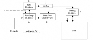
When blanketing gas enters the typical system (figure 1), the first-stage regulator (A) reduces inlet pressure from high to low. (This is not always required.) From here, the gas flows to the main control valve (E), which is closed when the tank is at or above its setpoint.
Supply is also piped to a filter regulator (
 supplying the pilot loading pressure - typically 10 psi - for actuation of the main flow control valve. This reduced pressure then floes through an orifice © and to the lower case of the main flow control valve as well as to the inlet of a sensing regulator (D).
Figure 1: Typical Tank Blanketing System Schematic The sensing regulator includes a diaphragm, which directly senses tank pressure. Its design, weighted and inverted, allows sensitivity to as close as 0.1 inch w.c. as well as the ability to sense and control vacuums at any pressure up to the inlet pressure. The outlet of the sensing regulator connects to the tank vapor space.
In operation, if tank pressure is below setpoint, the spring will move the sensing regulator diaphragm upward, opening the seat and allowing flow from the filter regulator through the orifice and into the tank. The size of the orifice limits the volume flowrate of gas to the tank. This minimal flow may be all that's necessary to satisfy a small demand.
However, as demand increases due to pump-out or thermal cooling, the pressure drops in the pilot loading line that connects © to main valve (E). This then reduces the pressure applied to the underside of the main valve diaphragm, which allows the spring to move the diaphragm, throttling the main valve open and supplying blanketing gas to the tank.
- May 31 2012 10:57 AM
- by proinwv

 FB
FB

