FB
FB


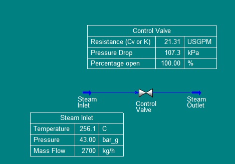
The odd part I am trying to figure out with these two heat exchangers is that IP steam temperature control valves (TC1 and TC2) are 100% open;however, the IP steam inlet flow rates are much lower than the design value for valve opening of 52%. For example, current steam inlet flow rate going to E1 is 2.70 tonnes/hr but according to design spec. sheet of the valve, at 52% opening, the flow rate should be 2.976 tonnes/hr (this is the maximum flow rate). As seen in the diagram, the two valves are controlled by outlet temperatures of amine acid gas and combustion air. The valve will open if the outlet temperatures are not meeting the required temperature.
I trended valve opening and flow rates from since these exchangers started to operate and found out that the two valves (TC1 and TC2) have always been open 100% but the flow rates have been changed. I also trended steam flow rates, amine acid gas flow rate, combustion air flow rate, and outlet temperatures of amine acid gas and combustion air. As the amine acid gas flow rate increases, the steam flow rate increases but the outlet temperature of amine acid gas decreases. The same trend occurs to combustion air. So I suspect that the heat exchangers are undersized that there is not enough heat transfer is happening in both exchangers but I am not sure if it is that case or if there is other areas I should pay attention. Please give any ideas that can shed some light onto me and to this problem. For more information, I took pressure survey on steam inlet lines for both exchangers and the pressure readings were as expected at around 4300kPa.
Currently, these exchangers operate fine but I am working on this to find ways to increase performance of the exchangers and do optimization.
E1 is one tube pass shell and tube heat exchanger. E2 is two tube pass shell and tube heat exchanger.
Any industrial experts out there please help me!! Thank you!
Attached Files
-
 heat exchanger data.pdf 123.57KB
1022 downloads
heat exchanger data.pdf 123.57KB
1022 downloads
-
PFD.pdf 7.06KB
728 downloads
Edited by bosun, 29 August 2012 - 12:13 AM.