Jump to content


Featured Articles

Check out the latest featured articles.

File Library

Check out the latest downloads available in the File Library.

New Article

Product Viscosity vs. Shear

Featured File

Vertical Tank Selection

New Blog Entry

Low Flow in Pipes- posted in Ankur's blog

0

Tee K-Value

crane

12 replies to this topic
Share this topic:
| More

#1 ezralh

ezralh

    Veteran Member

  • Members
  • 32 posts

Posted 14 April 2020 - 08:56 AM

Hi,


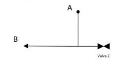
I would like to calculate pressure drop between point A and B. Valve z is closed. What K-value should I used for tee? Crane Technical Paper No. 410 M, suggest  K = 60ft for flow thru branch, however , since valve z is closed, all flow will be directed to B.


Cheres_tee_140420.JPG


Attached Files


#2 Bobby Strain

Bobby Strain

    Gold Member

  • Members
  • 3,529 posts

Posted 14 April 2020 - 09:05 AM

Look for tee as elbow.


#3 ezralh

ezralh

    Veteran Member

  • Members
  • 32 posts

Posted 14 April 2020 - 09:43 AM

Thanks Bobby.. that was what I did.. Just want to check with experts


#4 breizh

breizh

    Gold Member

  • Admin
  • 6,340 posts

Posted 14 April 2020 - 11:02 PM

Hi,

You should consider Mitre Bends with alpha = 90 degrees , K = 60*ft  as suggested

Crane Flows of fluids - TP No 410 M - page A-30

notes : 

There is an empirical formulation for Mitre Bend for alpha between 0 and 150 degrees 

           K= 0.42*Sin (alpha/2)+ 2.56 * Sin^3 (alpha/2)  from pipe flow a practical and comprehensive guide 

 same publication  : K=1.2  


Good luck .

Breizh


Edited by breizh, 14 April 2020 - 11:19 PM.


#5 latexman

latexman

    Gold Member

  • Admin
  • 1,686 posts

Posted 15 April 2020 - 10:20 AM

The 2018 Crane TP No. 410 (no M) has a more detailed method for tees and wyes than previous versions I've seen.  For a diverging 90o tee with Qbranch/Qcombined = 1 (your case), Kbranch = 1.7.


#6 Napo

Napo

    Gold Member

  • Members
  • 350 posts

Posted 15 April 2020 - 02:42 PM

Ezralh,


From Perry, 7th edition. K = 1.0.


Napo.

Attached Files


#7 breizh

breizh

    Gold Member

  • Admin
  • 6,340 posts

Posted 16 April 2020 - 09:24 PM

Hi,

To add to my previous answers a picture extracted from KSB pamphlet : K  tee= 1.28 when  Qa/Q =1 together with another reference for tee  Akatherm (table 7.5 and fig 7.4 ) : K=1.3 where V0/Vt =1 

Last data : french document : K=1.2 ref  Miller .

Good luck

Breizh 


Edited by breizh, 18 April 2020 - 08:03 PM.


#8 sarinvaibhav161286

sarinvaibhav161286

    Brand New Member

  • Members
  • 1 posts

Posted 06 October 2020 - 06:34 AM

The 2018 Crane TP No. 410 (no M) has a more detailed method for tees and wyes than previous versions I've seen.  For a diverging 90o tee with Qbranch/Qcombined = 1 (your case), Kbranch = 1.7.

 Hi Latexman,


In 2009 version of Crane, for Qbranch/Qcombined = 1  and Abranch/Acombined = 1  , the resistance coefficient of Kbranch for 90 deg diverging Tee was 0.78.

Has it really increased to 1.7 in 2018 edition of Crane?


#9 latexman

latexman

    Gold Member

  • Admin
  • 1,686 posts

Posted 06 October 2020 - 08:45 AM

I just double checked.  They have an equation and a graph.  Both say K = 1.69.


#10 breizh

breizh

    Gold Member

  • Admin
  • 6,340 posts

Posted 06 October 2020 - 11:52 PM

Hi,

To confirm :

                    K branch for diverging flow in tees and wyes (Qbranch/Qcombined =1 ) , 90 degrees 

                     was equal to   1. 09  in 2010 

                     and 1.69 in 2011 ,


                     data extracted from  TP 410M  (metric version)


hope it helps .


Breizh 


Edited by breizh, 07 October 2020 - 06:55 AM.


#11 katmar

katmar

    Gold Member

  • ChE Plus Subscriber
  • 668 posts

Posted 08 October 2020 - 04:42 AM

@latexman and @breizh - nobody has mentioned the size or the geometry of the tee, nor any mention of the Reynolds number. Do your references mention any influence by these factors?  I would imagine that the k value for a small threaded tee would be higher than for a large welded tee with a well radiused inner surface.


#12 breizh

breizh

    Gold Member

  • Admin
  • 6,340 posts

Posted 08 October 2020 - 04:53 AM

Hi Katmar ,

Please review the document attached ( TP 410 M /2011) with different tables associated .

Note : probably good to take a look at Handbook of hydraulic resistance by I.E Idelchik to confirm .


Breizh 


Edited by breizh, 08 October 2020 - 06:24 AM.


#13 katmar

katmar

    Gold Member

  • ChE Plus Subscriber
  • 668 posts

Posted 08 October 2020 - 08:44 AM

Thanks Breizh.  It seems that Crane does not take the radius of the inner surface into account.  I compared these values with Idelchik (3rd Ed), but even though I have an English translation it is VERY difficult to read.  On page 438 (Diag 7-10) Idelchik gives K values for tees with sharp corners (same as the Crane diagram). The value is 1.86 for the case of flow from the branch to only one side of the run, and with all diameters equal. This is quite close to the Crane value of 1.7


On page 462 (Diag 7-23 No. 4) Idelchik has tees with radiused corners - the translator calls these "wyes of improved shape".  For r/D (corner radius / pipe diameter) of 0.22 Idelchick gives a K value of 0.8 and for r/D of 0.07 the K value is 1.0.  From these values the radius is important in the determination of the K value, and this certainly reflects my own experience.


These values give me reassurance in the Darby 3K method that I used in AioFlo.  For a sharp cornered 1" tee and a velocity of 1 m/s the 3K method gives a K value of 1.7 - in line with the Crane value.  But if we go to a typical forged or cast tee with radiused corners - and using 2 m/s in a 8" pipe - AioFlo gives a K value of 1.06.


These differences will not have a large impact in practice, but they do highlight the improved performance of more modern methods like 3K.