Thanks for the reply.
All four heaters are operating at much too high stack temperatures. That could mean that there is a common cause.
Reply: Could be possible.
Hence my original question whether the heaters were modified to burn fuel oil instead of fuel gas, but you say that is not the case.
Then we need to look at another common cause: the BFW and its treating, the steam drum water and its treating, and the steam drum blowdown flowrate.
Reply: There is common BFW generated at Captive Power Plant (CPP) and distributed to all process units including NHT-CCR unit. So, BFW quality seems not the reason.
It could be that the steam generation as well as BFW preheat coils suffer from scale build-up (deposits of CaCO3, MgCO3 and other salts) inside the coils which, over time, severely reduces heat transfer.
Reply: We had opened the manifold at entry of BFW coils and pressurized water was forced back to the coils through the hydrotest nozzle in outlet. Water was coming out in pressure. However, any scaling inside coil can't be ruled out. We will get in cleaned in next turnaround.
Caused by insufficient water treating and/or insufficient blowdown, in combination with lousy distribution of BFW over parallel heaters.
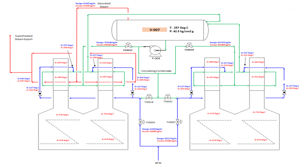
On the flow scheme the condition in steam drum V-007 is indicated as 257 oC at 42.5 kg/cm2.g.
42.5 kg/cm2.g is equal to 42.7 bara which would correspond with a temperature of 254 oC, not 257 oC.
(257 oC would correspond to a pressure of 44.7 bara or 44.5 kg/cm2.g, not 42.5 kg/cm2.g).
I would consider the pressure measurement more reliable than the temperature measurement.
Reply: Agreed. We will get the temperature and pressure indicator checked.
Lets look at F-003: according to your flow scheme the preheated BFW has an actual temperature of 319 oC. If that TI is correct than it would mean that the BFW preheat coil outlet is superheated steam instead of liquid water, resulting in scaling inside the coil.
Reply: We have checked through strap-on ultrasonic flowmeter in the inlet side, the bank wherein temp is 319 degC, flow was NIL.
Look also at F-001: according to your flow scheme the preheated BFW has an actual temperature of 258 oC, which is higher than the saturated temperature of 254 at actual steam drum pressure. If that TI is correct than it would mean that the BFW preheat coil outlet is steam/water or steam instead of only liquid water.
Reply: We have checked through strap-on ultrasonic flowmeter in the inlet side, the bank wherein temp is 258 degC, flow was NIL. There can be some error in temperature indication, but it was close to steam drum temperature, so didn't doubt it.
At other periods in the past years it may have been that F-002 and F-004 had these problems due to lousy BFW distribution between the heaters.
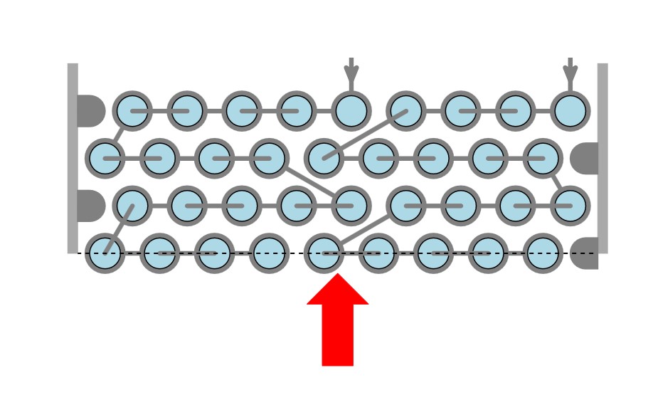
The BFW distribution can be adjusted by globe valves in the lines to each heater. I will call them GV1 through GV4, from left to right.
GV1 should be fully open and GV2 partly closed such that F-001 and F-002 have roughly the same stack temperatures and roughly the same BFW outlet temperatures.
GV3 should be fully open and GV4 partly closed such that F-003 and F-004 have roughly the same stack temperatures and roughly the same BFW outlet temperatures.
In general: the GV should be fully open for the heater with the highest stack and BFW temperature and partly closed for the other heater.
Reply: We had gone for the same solution in 2022 S/D and provided Globe valves in each bank inlet due to time constraint as providing GV in outlet meant we had to provide a PSV for safety. But even after providing the GVs, until the GV is completely closed in the bank wherein stack temp is on lower side, the temperature on other bank would not come down. So to avoid dry run of coils, we generally keep the GVs on both the banks fully open.
By closing TV0018 and TV0032 (by reducing their temperature setpoints) the stack temperatures should drop somewhat. In view of the high stack temperatures there is presently no need to increase BFW supply temperature.
Reply: Noted. BFW inlet temperature to Economizer was tried to be kept 14 degC higher than corresponding acid dew point temperature to avoid such acid condensation in cold zone. However, We will look into this aspect.
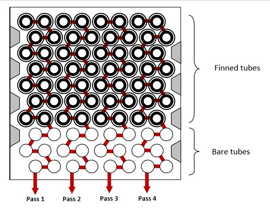
The design convection duty of F-001 / 002 is roughly 57 % steam generation, 19 % BFW preheat and 24 % steam superheat.
In Heaters F-003 and F-004 steam generation is roughly 76 % and BFW preheat is roughly 24 %. No steam superheat.
Too high stack temperature is likely caused by insufficient performance of the steam generation coils as these represent by far the biggest duty. That could mean that they might suffer from scaling. Flue gas maldistribution is not likely to occur in four different heaters as that could not result from a common cause.
Reply: The circulation flow rate in steam generations is ~ 84-85 % of design flow rate. margin still exits in pump to circulate more. But we didn't get any benefit on increasing the flow rate from earlier ~60 % to current 84 %, so we have held it at 84 %. However, we will try to come close to design flow rates and see if it increases steam generation. Further, we will again check for scaling removal from SG coils.
Earlier it was observed that even at lower circulation rate in steam generation coils, with increased fired duty, steam generation was high.
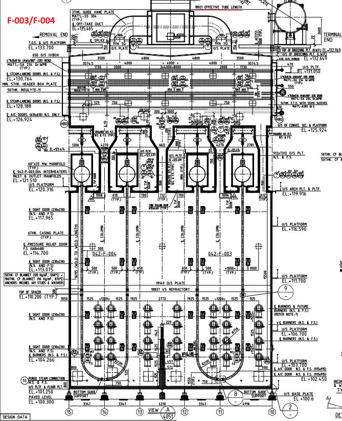
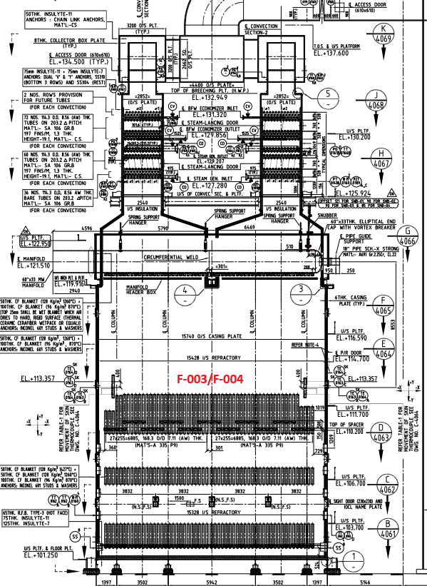
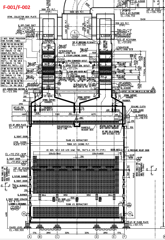
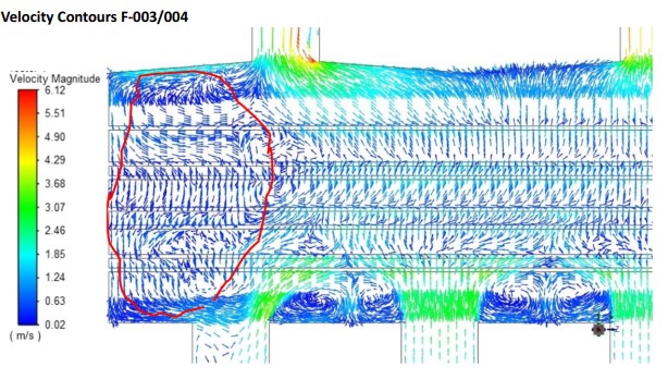
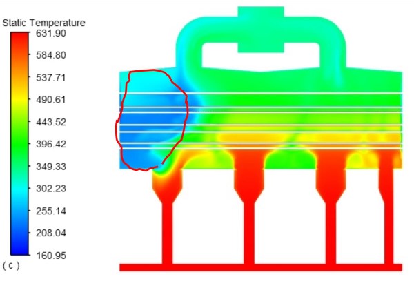
Regarding Flue gas maldistribution, it also looks to be a reason, you have also mentioned that major of the convection duty is picked up by SG coils. So, if overall current fired duty is lower than/near to turndown rate, can't flue gas maldistribution be a reason. I'm attaching the GADs for reference.
Less steam generation automatically results in less BFW drawn in by the steam drum, and less steam to be superheated, so less flue gas heat absorbed in their coils as well.
There is noting that you can do about scale until the next plant shut down when it can be removed. You may need to hire a specialized company for that.
Until then you can only prevent it from getting worse by having a close look at BFW and drum water chemical treatment, drum blowdown flowrate, analysis of BFW, drum water and steam from drum.
 FB
FB