Chemical and Process Engineering Resources
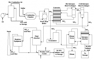
Packed towers are key components in sulfuric acid plants. Drying of the sulfur furnace air is necessary to avoid acid condensation and corrosion in downstream equipment and to minimize mist formation. Absorption of SO3 in the Interpass and Final Towers recovers the product sulfuric acid.
IntroductionGreat attention to detail is required in the design of packed towers to achieve the necessary absorption efficiency. In many ways, the sulfuric acid industry is unique in that packed towers of exceptionally large
It is suggested, however, to take into consideration the following points:
A standard three inch saddle is available from a number of suppliers at relatively low costs. This saddle has been used for over thirty years in the sulfuric acid industry. Only modest profit margins in making and supplying this type of packing can be expected, not sufficient to commission significant development work on packing performance in large towers, especially when competing suppliers would gain the benefit of the development at no cost. Contractors are in a similar position, leaving the owners as the only party likely to gain from development work. Where new packing is proposed, there is a need to compare it with existing packing to see if there is an improvement which justifies the development expense or makes the changeout of packing attractive to the owners. This economic reality has limited the introduction of new packing over the past twenty years.
Engineers involved in sizing towers have at their disposal a number of different techniques for tower sizing, ranging from rules of thumb based on gas velocity and irrigation rate, to dated theoretical work in the
 |
| Figure 1: A Typical Sulfuric Acid Plant Layout (Click to Enlarge) |
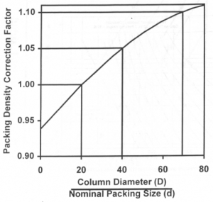
handbooks, to software programs from packing vendors, and finally to proprietary in-house design techniques. The resulting tower sizes vary significantly, as this paper will show. In addition, there is a need for design approaches which can be used with new packing for which there is little data. Most of the experimental work on packing pressure drop was carried out over forty years ago, almost exclusively in small pilot towers. Norton, for example, did much of their early work using thirty inch diameter towers while Koch used a thirty-six inch diameter tower. When the packing sizes were relatively small, the effect of the tower diameter on the packing density was minimal, but when larger packings were used in these pilot towers, there were significant edge effects and the void fraction in the test column was much larger than that found in large towers typical in acid plants with the same packing. The result was very optimistic predictions of pressure drop. Figure 2,
reproduced from a brochure published by VFF Industries, shows the relative number of pieces of packing per unit volume, the packing density, as a function of the ratio of the tower diameter to the characteristic dimension of the packing. The curve uses a reference packing density in a tower with a diameter twenty times the nominal size of the packing. For a three inch nominal size saddle, this would give a tower diameter of six feet. For a three foot tower, the packing density would be ninety seven percent of that of the reference tower, while for a twenty foot tower, the actual packing density would approach one hundred and ten percent of the reference case. The packing void fraction will vary accordingly with high packing densities resulting in low void fractions. The packed tower pressure drop and flooding limits are very sensitive to the void fraction, as will be shown later in this paper. It has been found that the pressure drop for a given large size packing in a plant scale tower can exceed twice the pressure drop measured in a pilot tower under identical process conditions.
 |
| Figure 2: Packing Density Correction Factor (Click to Enlarge) |
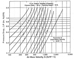
The Generalized Pressure Drop Correlation (GPDC) is the classic sizing method for packed towers and is used in many industries. It is, however, based mostly on the small pilot tower data. As long as the correlation is applied to small packing, it appears to give reasonable results, but when the performance of large packing in large towers is assessed, then the results appear overly optimistic. A second rule of thumb method is to size the tower based on a packing exit gas velocity of 8 ft/s with an acid irrigation rate of 10 USGPM/ft2. Most often the velocity used in sizing the tower is that of the gas leaving the packing. Different techniques should be applied to the tower bottom depending on the temperature of the inlet gas and the relative acid flow. A third sizing approach is to use the published pressure drop curves for the air and water system which are publicized in the suppliers'' literature. Figure 3 shows one such plot published by U.S. Stoneware. This approach is more practical but, as previously discussed, the data were again mostly developed in small pilot towers, even when large packing was studied. On the basis of proprietary design approaches, one from a packing supplier, and the second from a chemical company, a design approach was developed by CECEBE based on ideas originally proposed by Dr. Max Leva. Field data were carefully taken in full sized towers to refine the correlations and design methods. The method of Dr.
 |
Figure 3: Pressure Drop versus Gas Rates |
Leva starts with dry bed pressure drop, which is then corrected for the liquid flow through the packing and also for loading. With moderate gas flows and pressure losses, the incremental increase in pressure drop due to liquid irrigation depends on the liquid flow but does not change with gas velocity. Greater liquid flow causes greater liquid hold-up and higher interstitial gas velocities. These two effects combine to result in higher pressure drop. In this range of moderate gas and liquid flow rates, pressure drop curves for irrigated packing run parallel to the dry gas pressure drop curve. Further increases in gas and liquid flow, beyond a critical limit called "loading point", result in a rapid increase in the liquid hold-up due to spray re-entrainment and causes increased pressure loss. Eventually, the liquid hold-up fills a significant part of the packing void and it becomes difficult to force gas flow through the packing. The tower ultimately floods.
The various design approaches described earlier have been used in this paper in a standard absorber to predict the tower size on the basis of operating with standard packing. In addition, tower sizes were developed for both the HPTM Saddle Packing developed by CECEBE Technologies and the Flexeramic® Structured Packing developed by Koch.

 FB
FB

0 Comments