Chemical and Process Engineering Resources
Comparison of Packing
When new towers are designed,an allowance for fouling should be made by adjusting the void fraction using Equation 2![]() , for example by assuming that the void fraction is lowered by fouling. Similarly, when repacking a tower, the old packing probably will have a lower void fraction due to fouling or shrinkage, than when it was originally installed.
, for example by assuming that the void fraction is lowered by fouling. Similarly, when repacking a tower, the old packing probably will have a lower void fraction due to fouling or shrinkage, than when it was originally installed.
 |
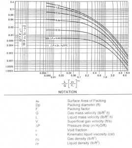
| Figure 6: Generalized Pressure Drop Correlation (Click to Enlarge) |
The pressure drop and power saving associated with repacking as calculated by normal techniques will probably underestimate the benefits. Similarly, newer packings, for which full size tower data are available, can be more rigorously screened for economic viability. In many cases, the power savings from repacking with a lower pressure drop packing will often pay for packing premium costs in one or two years. If there are fewer chips, further savings will result, but these are harder to quantify. In general, the cheapest packing available is probably the worst bargain for the owner unless the towers had been grossly oversized to start with. This point has not yet been recognized by many owners.
Two-phase flow has been studied for many years, mostly in small towers. The common design methods advocated can generate significantly different solutions for the same packed tower duty depending on the methods used. Several different approaches to packed tower design were reviewed in preparing this paper.
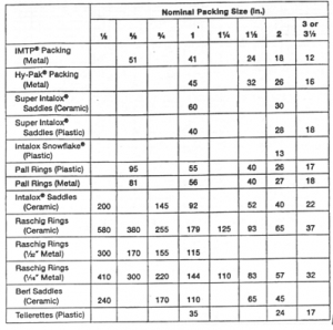
Let us consider now the different methods of tower sizing in more detail. The most common approach is that described in Perry''s Chemical Engineers'' Handbook, 6th Edition. The GPDC is shown in Figure 18-38 in this reference and has been copied here from another reference as Figure 6. The packing factor "F" for Figure 6 are provided in Table 2. The data on which this figure is based were obtained in the fifties and sixties using a thirty inch diameter column. Packing factors are shown in a separate table. Sherwood, Holloway, and Eckert were the the primary contributors to this work but Eckert is responsible for the form as it appears in Perry''s. Initially the key characteristic of the packing was the ratio of the interfacial area (a) of the packing to the void fraction in the bed (a/![]() 3). Leva has also been given credit for this correlation, but he does not claim credit nor does he recommend it.
3). Leva has also been given credit for this correlation, but he does not claim credit nor does he recommend it.
It is now known that using data derived from large packing in small towers introduces errors both in the interfacial area, more saddles in a cubic foot than predicted, and lower void fraction. For the same reason, drastically revised packing factors for the large packings might bring the correlations in line but to our knowledge, this correction has not been proposed. Such correction will likely result in a doubling of the packing factor for three inch saddles.
 |
A second method for design is to use gas pressure drop curves measured in water-air systems for the various packings and commonly included in packing brochures. A sample is shown in Figure 3![]() . These graphs are specific to the packings in question. U.S. Stoneware provided a book of such curves, but unfortunately the three inch saddle had not been developed at that time so the only graphs in the Norton brochures are quite small. The data come again from small test towers. Adjustments of the data to larger tower is required.
. These graphs are specific to the packings in question. U.S. Stoneware provided a book of such curves, but unfortunately the three inch saddle had not been developed at that time so the only graphs in the Norton brochures are quite small. The data come again from small test towers. Adjustments of the data to larger tower is required.
A third proprietary approach follows more closely that suggested of Leva in calculating dry bed pressure drop with a correction factor for the effect of irrigation. The empty tower velocity head lost per unit height is calculated from the liquid flow per unit area and two proprietary constants. G. Morris of ICI, the designer of this technique, did not recommend using it with high gas flows and pressure drops and several
constants are involved for each packing size. In our review, the approach of Leva is simpler with the dry bed pressure drop calculation involving the empty tower liquid velocity and one constant for each packing. An exponential term including the liquid mass velocity in the empty tower is then used to correct for the impedance of gas flow by the liquid. The correction for acid flow will range as high as 100% in main absorbers with high liquid flows and 50% in drying towers and final absorbers. Morris adjusted his void fractions to towers with diameters twenty to thirty times the packing size which corresponds to six to eight feet, a step in the right direction, though not far enough.
Many engineers, over the years, have developed correlations and programs for packing pressure drop from the published test tower data and used the correlations to predict pressure drop. One such program, generally made available by a supplier of packings, has been used to evaluate pressure drop for the test case for both standard 3" saddle packing and a structured ceramic packing.
Several comments need to be made about the data used in these evaluations. The first is that the number of pieces of packing in a unit volume of tower vary significantly with the ratio of tower diameter to packing size as was shown in Figure 2![]() . Essentially all of the data used in the correlations were developed in towers in the 2.5 to 3 foot range. When the packing was small such as 1", the number of pieces per
. Essentially all of the data used in the correlations were developed in towers in the 2.5 to 3 foot range. When the packing was small such as 1", the number of pieces per
unit volume was reasonably high and usable in large towers. With large saddles, however, the packing density was much lower than found in full size towers and the pressure losses were much lower. In packing supply quotes, the "so-called" settling allowance is simply a correction factor to ensure there are enough pieces of packing to fill the tower. In many cases know to the authors, packing purchased to refill a tower of specified volume was found to be insufficient to physically fill the tower, even though the exact tower dimensions were given to the supplier. A "shrinkage" of 1.5 ft out of a 12 ft packing height was not unusual, and often caused a very embarrassing start-up situation. It is on the basis of this experience that CECEBE went through the trouble of making a saddle count when packing a number of new towers. Similar data on standard saddles would also be very useful. It is also suggested that the quantity of packing normally supplied by manufacturers to fill a cubic foot of tower will actually normally not fill a cubic foot in a large tower and owners might have a legitimate case for a better definition of what is needed to fill a cubic foot of tower volume.
The tower diameter for the standard three inch saddle using the different design techniques are shown in Table 3 while the diameters for different packings are shown in Table 4.
What the above tables show is that various methods available for tower sizing give widely different answers (Table 3) and that there is significant capacity difference between different packing (Table 4). This capacity difference can be exploited when a plant is being expanded by repacking with higher performance packing.

 FB
FB

0 Comments