 FB
FBChemical and Process Engineering Resources

Numerous articles have been published regarding the advantages of compact heat exchangers. Briefly, their higher heat transfer coefficients, compact size, ease of service, cost effectiveness, and their unique ability to handle fouling fluids make compact exchangers a good choice for many services.
Plate Heat Exchanger Parts and Service Do you need parts or service for your plate heat exchanger? Maybe you just have a technical question. Give us a call at (804) 370-3855 or complete the email form below and we'll be happy to help. |
A Quick Look at the Basics
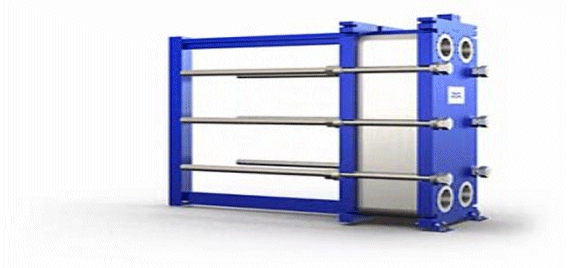
Plate heat exchangers consist of pressed, corrugated metal plates fitted between a thick, carbon steel frame. Each plate flow channel is sealed with a gasket, a weld, or an alternating combination of the two. It is not uncommon for plate and frame heat exchangers to have overall heat transfer coefficient that are 3-4 times those found in shell and tube heat exchangers.
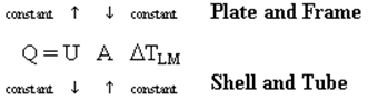 | Eq. (1) |
Specifying a Plate and Frame Heat Exchanger
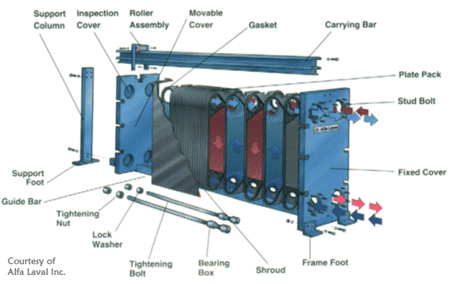 |
| Figure 1: Parts Structure for a Plate Heat Exchanger |
Engineers often fail to realize the differences between heat transfer technologies when preparing a specification. This specification is then sent to vendors of different types of heat exchangers. Consider the following example:
A process stream requires C276 material to guard against corrosion. The stream needs to be cooled with cooling water before being sent to storage. The metallurgy makes the process stream an immediate candidate for the tubeside of a shell and tube heat exchanger. The cooling water is available at 80 °F and must be returned at a temperature no higher than 115 °F. The process engineer realizes that with the water flow being placed on the shellside, larger flowrates will enhance the heat transfer coefficient. The basis for the heat exchanger quotation was specified as follows:
| Tubeside | Shellside | |
| Flow Rate (GPM) | 500 | 1800 |
| Temperature In (°F) | 280 | 80 |
| Temperature Out (°F) | 150 | 92 |
| Allowable Pressure Drop (psig) | 15 | 15 |
According to the engineer's calculations, these basic parameters should provide a good shell and tube design with a minimum amount of C276 material (an expensive alloy). The completed specification sheet is forwarded to many manufacturers, including those that could easily quote plate and frame or another compact technology. A typical plate and frame unit designed to meet this specification would have about 650 ft2 of area compared to about 420 ft2 for a shell and tube exchanger. A plate and frame unit designed to the above specification is limited by the allowable pressure drop on the cooling water. If the cooling water flow is reduced to 655 GPM and the outlet water temperature allowed to rise to 115 °F, the plate and frame heat exchanger would contain about 185 ft2 of area. The unit is smaller, less expensive, and uses less water. The load being transferred to the cooling tower is the same.
The theory that applied to the shell and tube heat exchanger (increasing water flow will minimize heat transfer area), works in exactly the opposite direction for compact technologies. The larger water flow actually drives the cost of the unit upward. Rather than supplying a rigid specification to all heat exchanger manufacturers, the engineer should have explained his goal in regards to the process stream. Then he could have stated the following:
The process stream is to be cooled with cooling water. Up to 2000 GPM of water is available at 80 °F. The maximum return temperature is 115 °F.
This simple statement could result in vastly different configurations when compared with the designs that would result from the original specification.
5 Comments
my only query is that graphs given here ,can they be used for bloc welded plate heat exchanger designing ?.
Sir,
Very nice article and very helpful.
But my query is that how these graph comes can you
sir please provide some baics about these.
Thanks
Ashish
Hindalco
These are generalized correlations that I put together when I worked for Alfa Laval. They are appropriate for early phase design.
Dear Sir,
My NTUcold is calculated to be 0.09 based on temperature difference of 4 C (37-33)C and LMTD of 40.86C. For this NTU there does not seem to be a graph.
The cooling water temperature limits are fixed here based on cooling tower's profile.