 FB
FB
 6 votes
Perforated Pipe Distributor Sizing Calculations
16 May 2013
 Perforated Pipe Distributors have been discussed many times on “Cheresources”. How to design a perforated pipe distributor also known as a sparger has been a frequent question on the forum. Some general replies without providing in-depth methodology of sizing a distributor can be seen in the queries raised.
Perry’s Handbook (8th Edition) has a brief sub-section on perforated pipe distributors in Section 6, Fluid & Particle Dynamics which I had gone through critically but which was not to my satisfaction.
Since I do have a penchant of finding and developing engineering calculations, I was continuously on the look-out for something related to perforated pipe distributors. Last week I struck gold, when I found a company design manual providing detailed calculations for perforated pipe distributors. I had a critical look at it and found it to be better than anything I had found and read earlier related to perforated pipe distributors. I could even develop an excel workbook for perforated pipe distributor from this very informative design procedure.
Today’s blog entry is meant to provide the stepwise calculations for a perforated pipe distributor including the design equations. Both liquid and gas pipe distributors are covered. Gas pipe distributors follow the same design steps as that for liquid pipe distributors except for some minor variations in the design procedure. Both Metric units and USC units have been provided in the methodology.
Let us straight away get to the steps for sizing a Perforated Pipe Liquid distributor:
Step 1:
Initially set the pipe size of the pipe distributor, same as the pipe size feeding the pipe distributor
Step 2:
Calculate the Reynolds number, Rei, of the inlet stream to the pipe distributor using the following equation:
Metric Units:
Rei = 1.27*Q*ρ / (d*μ)
USC Units:
Rei = 50.6*Q*ρ / (d*μ)
where:
Q = Volumetric flow Rate, liters/s (gpm)
ρ = Liquid Density, kg/m3 (lb/ft3)
d = inside diameter of pipe, mm (inch)
μ = Liquid Viscosity, Pa.s (cP)
Step 3:
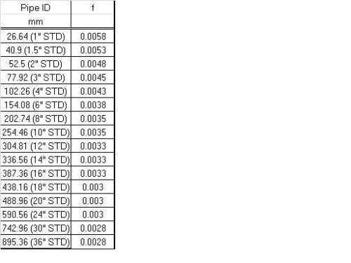
Find the fanning friction factor f (dimensionless), for the given flow regime. For turbulent flow some values for fanning friction factor based on pipe size are provided in the attached table.
Step 4:
Calculate the Kinetic Energy per unit volume of the inlet stream, Ek, kPa (psi) from the following equations:
Metric Units:
Ek = 810*α*ρ*Q2 / (d4)
USC Units:
Ek = 1.8*10-5*α*ρ*Q2 / (d4)
where:
Ek = Kinetic energy per unit volume of the inlet stream, kpa (psi)
α = velocity correction factor (use α = 1.1 for turbulent flow and 2.0 for laminar flow)
Step 5:
Calculate the pressure change ΔPp along the distributor pipe due to friction and momentum recovery from the following equations:
Metric Units:
ΔPp = ((4000*f*L*J/α*d) – 1)*Ek
USC Units:
ΔPp = ((48.0*f*L*J/α*d) – 1)*Ek
where:
f = fanning friction factor, dimensionless
L = Length of perforated distributor pipe, m (ft)
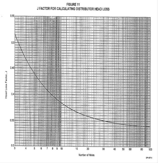
J = dimensionless factor (Use J = 0.35 as an initial value)
Step 6:
Find the required pressure drop, ΔPo across the distributor holes by multiplying the greater of Ek or ΔPp by 10. If the calculated value of ΔPo is less than 1.75 kPa (0.25 psi) make it equal to at least 1.75 kPa (0.25 psi).
Step 7:
Calculate the required total area of the pipe distributor holes, Ao, using the following equations:
Metric Units:
Ao = 22.3*(Q / C)*sqroot (ρ/ΔPo)
USC Units:
Ao = 3.32*10-3*(Q / C)*sqroot (ρ/ΔPo)
where:
Ao = Total required hole area, mm2 (in2)
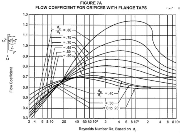
C = flow coefficient, dimensionless (as a first value consider C = 0.60)
Step 8 (Guidelines for choosing hole diameter and hole-to-hole linear distance):
a. Minimum hole diameter ≈ 1/2-in. (13 mm) to avoid plugging and to limit the number of holes to a reasonable value. In very clean service, smaller holes may be considered, but in severely fouling service, 1/2-in. (13 mm) holes may be too small.
b. Maximum hole diameter = 0.2 times inside diameter of distributor.
c. The ratio of hole diameter, do, to inside pipe diameter, di, should be between 0.15 and 0.20 when the criterion ΔPo = 10 Ek is used. If it is necessary to use do /di < 0.10, then make ΔPo = 100 Ek.
d. To provide sufficient pipe strength, the minimum distance (edge-to-edge) between adjacent holes should approximately equal the hole diameter.
e. Within the limitations imposed by the above requirements, a larger number of small holes are preferred over a smaller number of large holes.
f. If slots are used instead of holes, the slot width should be at least 1/2-in. (13 mm).
Step 9:
The value of Rei / n should be greater than 4000. If it is not, then a new flow coefficient value "C" should be calculated from the attached chart. Instead of Re shown on the x-axis of the chart use Rei / n for reading the flow coefficient of the chart.
Step 10:
Using the calculated number of holes, find the factor "J" from attached chart and compare this with the assumed value of 0.35. If this revised value of J affects the value of ΔPo by more than 10%, substitute the revised value of J in equation given in Step 5 and repeat the steps starting from calculation of ΔPp.
Perforated Pipe Gas Distributor:
Step 1:
Initially set the pipe size of the pipe distributor, same as the pipe size feeding the pipe distributor
Step 2:
Calculate the Reynolds number, Rei, of the inlet gas stream to the pipe distributor using the following equation:
Metric Units:
Re = 1270*W*ρ / (d*μ)
USC Units:
Re = 6310*W*ρ / (d*μ)
where:
W = gas flow Rate, kg/s (lb/h)
ρ = Liquid Density, kg/m3 (lb/ft3)
d = inside diameter of pipe, mm (inch)
μ = Liquid Viscosity, Pa.s (cP)
Step 3:
Find the fanning friction factor f (dimensionless), for the given flow regime. For turbulent flow some values for fanning friction factor based on pipe size are provided in the attached table.
Step 4:
Calculate the Kinetic Energy per unit volume of the inlet stream, Ek, kPa (psi) from the following equations:
Metric Units:
Ek = 8.10*108*α*W2 / (ρ*d4)
USC Units:
Ek = 0.28*α*W2 / (ρ*d4)
where:
Ek = Kinetic energy per unit volume of the inlet stream, kpa (psi)
α = velocity correction factor (use α = 1.1 for turbulent flow and 2.0 for laminar flow)
Step 5:
Calculate the pressure change ΔPp along the distributor pipe due to friction and momentum recovery from the following equations:
Metric Units:
ΔPp = ((4000*f*L*J/α*d) – 1)*Ek
USC Units:
ΔPp = ((48.0*f*L*J/α*d) – 1)*Ek
where:
f = fanning friction factor, dimensionless
L = Length of perforated distributor pipe, m (ft)
J = dimensionless factor (Use J = 0.35 as an initial value)
Step 6:
Find the required pressure drop, ΔPo across the distributor holes by multiplying the greater of Ek or ΔPp by 10. If the calculated value of ΔPo is less than 1.75 kPa (0.25 psi) make it equal to at least 1.75 kPa (0.25 psi).
Step 7:
Calculate the required total area of the pipe distributor holes, Ao, using the following equations:
Metric Units:
Ao = 2.24*104*(W/C*Y)*(1 / sqroot (ρ*ΔPo))
USC Units:
Ao = 2.24*104*(W/C*Y)*(1 / sqroot (ρ*ΔPo))
where:
Ao = Total required hole area, mm2 (in2)
C = flow coefficient, dimensionless (as a first value consider C = 0.60)
Y = Gas expansion factor, dimensionless
Y is calculated as follows:
Y = 1 - (0.41 + 0.35*β4)*ΔPo/(k*P) for ΔPo/P <0.37 -------(i)
Y = Y0.37 - 0.37*( (ΔPo/P) - 0.37) for ΔPo/P >0.37 --------(ii)
where:
P = Pressure at the inlet of the gas distributor, kPa (abs) (psia)
k = ratio of specific heats, Cp / Cv
β = ratio of hole to the perforated pipe inside diameter (specified earlier as a value between 0.15 to 0.20)
Y0.37 = value of Y calculated using eqn (i) with ΔPo / P equal to 0.37
Steps 8,9 & 10: These remain the same as for Perforated Pipe Liquid Distributors.
This has been a rather detailed description on how to size a perforated pipe distributor and I am hoping that readers and members of "Cheresources" find it useful and can build a excel workbook using the equations and method provided. Please do refer the attachments while reading the text of this blog entry.
Looking forward to comments from the knowledgeable forum members.
Regards,
Ankur.


Hi sir,
i need your suggestions on, whether can i follow the above method to calculate number of holes in each of the branch in distributor of sparger pipe. My aim is to see that pressure drop of steam is equal till the last branch, so that steam is not rushed in to few branches. i assume this equal pressure drop across each hole in each branch shall make steam properly distributed across the sparger and its branches and set of small hole in each branch.
This sparger pipe is burried in near saturated water by about 800 - 1000 mm. This is for deaerator in power plants
I am new to this site so unable to attach rough sketch.
Need your suggestion on the above issue.
thanking you
sandeep