 FB
FB


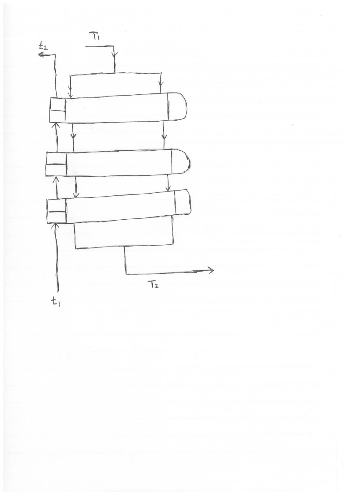
I am having a problem in estimating the correction factor of MTD (FT) for the attached heat exchanger configuration. The known parameters are t1, t2, T1 & T2.
Any one can guide me to the approperiate FT chart or formula?.
|
|

Gold Member
Posted 16 June 2016 - 02:28 AM
Gold Member
Posted 16 June 2016 - 02:49 AM
Sorry for multiposting that was by mistake while clicking post topic I thought it was not posted.
Gold Member

Posted 16 June 2016 - 05:20 AM
I am not sure whether you have understood significance of Ft factor and where it is to be used.
However, in order to calculate Ft factor, you are required to calculate LMTD & caloric temperature. Based on graph as per exchanger geometry, you can get Ft factor.
Forum may be able to help you, if you describe your problem in detail & your understanding clearly about the assignment.
Gold Member

Posted 16 June 2016 - 02:28 PM
You can find LMTD correction factor charts for unusual shell types in the following EXCEL spreadsheet:
Process Heat Transfer by Art Montemayor. IT is downloadable and is It s located in the file library.on this website.
Gold Member

Posted 16 June 2016 - 06:21 PM
Hi Said ,
As per Srfish'advice , consider the great resource attached .
Breizh
Gold Member
Posted 19 June 2016 - 02:58 AM
Gold Member

Posted 19 June 2016 - 02:24 PM
Maybe, maybe not. The arrangement you show suggests that the shell side is condensing vapor, and the tube side a single phase cooling media. You need to see the shell baffle detail to get the right configuration. It seems to be primarily cross flow on the shell side.
Bobby
Gold Member
Posted 20 June 2016 - 12:09 AM
 HE-Datasheet3.pdf 687.41KB
548 downloads
HE-Datasheet2.pdf 1.37MB
504 downloads
HE-Datasheet1.pdf 1.45MB
604 downloads
HE-Datasheet3.pdf 687.41KB
548 downloads
HE-Datasheet2.pdf 1.37MB
504 downloads
HE-Datasheet1.pdf 1.45MB
604 downloads
Gold Member
Posted 20 June 2016 - 09:57 AM
HE-Datasheet1.pdf shows that they are TEMA type DXU heat exchangers. The X indicates cross-flow heat exchangers. You can find LMTD correction factor charts for cross-flow in the Heat Exchanger Design Handbook.
Gold Member
Posted 21 June 2016 - 12:52 AM
Many thanks to srfish for taking my attention towards points mentioned in his post. Hence, I have removed my earlier post.
As a academic curiosity, I run HTRI for given datasheet & noted below.
No. of exchanger in series : 3
Exchanger No. : Hot Inlet, ºC: Hot Outlet, ºC : Cold Inlet, ºC : Cold Outlet, ºC
1 : 340ºC : 280.8ºC : 257.2ºC : 310ºC
2 : 280.8ºC : 235.4ºC : 216.6ºC : 257.5ºC
3 : 235.4ºC : 200ºC : 185ºC : 216.6ºC
I guess, in absence of above data, Said Salim was experiencing problem of estimating Ft factor. Please correct me if I am wrong.
However, concern still remains is how to estimate these terminal temperatures for DXU type configuration, without help of HTRI.
Gold Member
Posted 21 June 2016 - 04:25 AM
Gold Member
Posted 21 June 2016 - 06:17 AM
Well. Now when you have terminal temperature with you for each exchanger in series, you may refer to applicable graphs for exchanger geometry wherein you can read Ft factor directly based on terminal temperature. Well known source can be Kern Book.

Gas-Liquid Pipe Flow Friction Loss CorrectionStarted by Guest_Huba_* , 18 Dec 2025 |
|
|
||
Colebrook's Equation - Friction FactorStarted by Guest_breizh_* , 10 Nov 2024 |
|

|
||
C Factor For Erosional Velocity For Multi-Phase Flow (Nat Gas/ ProduceStarted by Guest_Sam11_* , 10 Sep 2024 |
|

|
||
Determining The F-Factor Following The Api 2000Started by Guest_Hachimi_* , 06 Sep 2024 |
|
|
||
Environmental Factor "f" Calculation In Psv Fire CaseStarted by Guest_mahmooddalvi09_* , 17 Aug 2024 |
|
|

