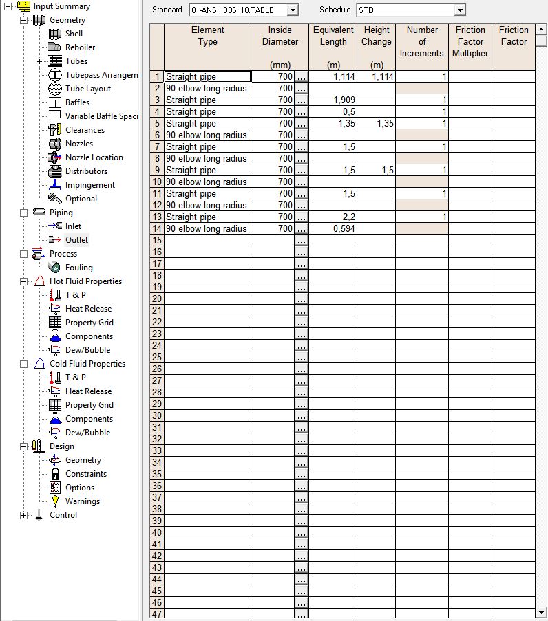
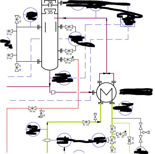
|


Htri, Modeling Of An Thermosyphon Reboiler
#1
Posted 26 May 2017 - 10:09 AM
#2
Posted 26 May 2017 - 02:48 PM
Why do you need to rate the exchanger? You certainly don't need the rigorous calculation to model the fractionator. Maybe you should reassess the scope of your work. And the arrangement you describe seems strange. Maybe you can provide several views of the exchanger.
Bobby
#3
Posted 26 May 2017 - 03:49 PM
I want to know how much straight run gasoline i can involve to the existing fractionation column. To solve this task I have made a PRO/II modeling of the existing column and I also want to rate the exchanger (the Fractionator's reboiler). After these steps, I will know how much overdesign I have and also should I buy new equipment or not. All I want to know is how to set the pipe line (Pipe 2,3,4) from HE to column in HTRI (detailed piping--->outlet). Here is an image: https://ibb.co/i9BFTF
Edited by Nik Lebedev, 26 May 2017 - 06:37 PM.
#4
Posted 26 May 2017 - 07:26 PM
The arrangement you show looks like I expect for a condenser, not a reboiler. You might want to check your exchanger drawings again to confirm the arrangement. And, you need to get data from the operating exchanger as confirmation. Actual data is always better than rating.
Bobby
#5
Posted 27 May 2017 - 05:49 PM
The arrangement you show looks like I expect for a condenser, not a reboiler. You might want to check your exchanger drawings again to confirm the arrangement. And, you need to get data from the operating exchanger as confirmation. Actual data is always better than rating.
Bobby
It's a reboiler, look at drawings which a attached. Sorry but i need help in HTRI, the question/problem is above.
#7
Posted 28 May 2017 - 11:55 AM
Nik:
I am familiar with this type of horizontal thermosyphon reboiler. I’ve worked on two previous designs. One was as a repair and the other was a new, up-graded design for a distillation column when I worked on DuPont projects back in 1993. I managed the process design and project execution.
We did the process design and HTRI details exactly as you show the configuration. The reason for the two shell side 2-phase outlets is due to the shell side pressure drop which had to be kept very low to allow for natural thermosyphon circulation. This is a trade off typical of horizontal thermosyphons. A horizontal configuration was specified because operations personnel required easy and rapid maintenance access to the shell side, so a vertical model was eliminated.
My memory is fuzzy on the design issues, but I remember that the problem was not the HTRI rating. The problem was ensuring that the piping pressure drop was low and that the piping layout allowed for equal flow through both of the 2-phase outlets. We rated the reboiler with HTRI and did all outlet (and inlet) piping calculations manually. The unit worked, but I recall we had a lot of problems in predicting the actual recirculation flow rate around the thermosyphon because of the 2-phase flow within part of the reboiler’s shell side and in the outlet piping layout. As I recall, HTRI did not require any input on the type and extent of external piping design. Therefore, I don’t know what difficulty you are having with HTRI’s rating design. I would follow Bobby’s suggestion of treating it as a standard J shell with equivalent inlet and outlet piping for the configuration.
My suggestion is to be very careful of all your pressure drops and be wary of how much vaporization rate you can apply with in this type of design. For some details on this application, read the explanation by A. Kayode Coker in his “Ludwig’s Applied Process Design for Chemical and Petrochemical Plants” volume 3, 4th edition, pages 376-278. His drawing on Figure 15-218 shows the same identical sketch and configuration as yours. I hope this helps.
#9
Posted 29 May 2017 - 02:30 AM
Art:
Hi, thanks for quick reply. I have understood, but can you tell me is it correct to set outlet detained piping like that.
Drawings are below.
https://ibb.co/fVp1Lv
https://ibb.co/i1k5DF
#10
Posted 29 May 2017 - 10:49 AM
Nik:
What do you mean by the term "detained"?
Do you mean "reduced", "off-set", or lengthy?
In any type of thermosyphon design, you must install the size and amount of piping that conforms to the pressure drop restrictions on the required boil off amount that takes place in the reboiler. In other words, my experience has shown that the key to this type of reboiler is to facilitate - or ensure - that you don't install excessive piping constraints in both the inlet and (especially) the outlet piping. Remember, you are totally dependent for fluid flow based only on gravity and the thermosyphon effect created. You have no other means to obtain the required flow rate through the reboiler. This is not a pump-around reboiler where you can adjust the flow rate to your heart's content.
As I stated previously, there are trade-offs here (as in all engineering designs) and the need to locate the reboiler at grade level, process flow in the shell side, and local piping space allowance gives you potential problems in keeping your process pressure drops within the allowable range. Sometimes, in the case of a new installation, you may have to increase the tower sump level or raise the tower more in order to obtain the natural circulation rate that you need for design purposes. You certainly want to keep your piping as simple and short-length as possible. I certainly would do rigorous pressure drop calculations on all the surrounding piping - especially the 2-phase outlet.
Reply to this topic

Similar Topics
Levels For Kettle Type ReboilerStarted by Guest_RajD_* , 04 Apr 2025 |
|
![]() |
||
Modeling Liquid Metals In Aspen PlusStarted by Guest_AnthonyB_* , 03 Apr 2025 |
|
![]() |
||
Modeling Liquid-Liquid Membranes In Aspen PlusStarted by Guest_bodinjas_* , 18 Mar 2025 |
|
![]() |
||
Phe As ReboilerStarted by Guest_Chemeng40_* , 20 Feb 2025 |
|
![]() |
||
![]() How To Replace Existing Reboiler With A Thermosyphon Reboiler In HysysStarted by Guest_tomr91_* , 04 Feb 2025 |
|
![]() |