The exchanger appears to be a brazed aluminum heat exchanger with two cold streams and two hot streams. These streams do not work independently. The hot streams are coming from another multi-stream exchanger and there is at least one additional multi-stream exchanger prior to that one. The demethanizer feed system with its multiple exchangers and flash drums is very integrated and should be evaluated as a system. A steady state model of the system is difficult because of the integration. Demethanizer feed system is tough to model and will take some time. The close internal temperature approaches in the exchangers give results that are not intuited by looking at just the inlet and outlet temperatures. Building a model for design is easier than for rating an existing unit. In your case, I would first find the design basis for your plant and model that to match the design material balance. Your cracking yield will be different and the design basis may be far from how the plant currently operates, but you need to verify your model. Then you can try to change the model conditions toward your operation.
The only problem you mentioned is the variableness in the ethane refrigeration system. What trouble does this cause? Is it only a problem seen in the refrigerant loop or do you see a problem in the feed to the demethanizer?
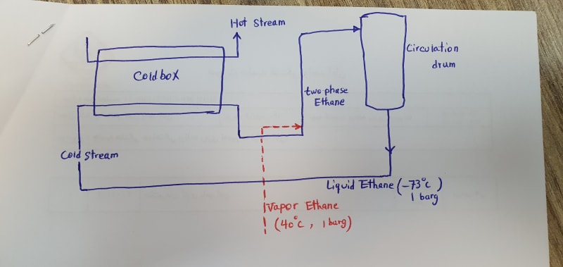
Often the hardest part of troubleshooting is determining the real problem and formulating the right questions to answer. The original post assumed there was a piping problem in the ethane system and claimed the ethane return to the drum is two phase. What evidence do you have that the return is two phases? Do you think it was designed to normally have two phases? What do you base that conclusion on? According to your recent PFD, the other cold stream leaves the exchanger at 43 C.Why wouldn't the ethane stream have that temperature also? Could ethane have two phases at that temperature and pressure? Have you noticed that both hot streams exiting this exchanger are colder than the cold ethane stream? Is the ethane stream transferring heat in just a portion of the exchanger? There is much thought put into the exchanger design and piping design inside a cold box and until you understand why the designers made the choices they did, it is presumptuous to say they were wrong.
I have designed demethanizer feed systems. This exchanger is the trickiest one to model and design. Concentrating on the unfamiliar ethane piping is to miss the larger picture. Understand the process and figure out what the real problem is. Modeling really helps in this complicated system. There may be no one in your entire plant who really understands how this system works.
 FB
FB


 20211110_092834_o5rbu7.jpg 35.21KB
0 downloads
20211110_092834_o5rbu7.jpg 35.21KB
0 downloads


