 FB
FB


Hello everyone, it's a pleasure to be part of this forum.
I'm in doubt about filling incondesdibles in a distillation column that I'm adapting. any contribution will be welcome.
Well then, we have a bubble cap tray column, in which approximately 500kg/h of vent comes out of the top. This column has a reflux ratio of 1.9, and in the condenser, we have a vacuum of 20mmHg (dry screw pump). My question is the following:
the product to be distilled is a mixture of esters (miscible fractions), however one of them is pure at the condenser pressure (20mmHg and at the reflux operating temperature (65°C is completely vapor -although the mixture is not as shown by the Simulation: I dimensioned a BEM theme C tower water exchanger that manages to fully condense the mixture, however I know that in practice the condensate in the exchanger that will fall into the vessel will reach the pump.
For better understanding. At the column outlet, I dimensioned a theme C condenser that is connected to a reflux vessel below (via a dip tube). The steam inlet is in the hull and this exchanger at the outlet is connected to the reflux vessel (pressure equalization).
It is in the reflux vessel that I have the connection to the evacuation pump, and this is what worries me, because at 20mmHg and 65°C I know that a minimum capture of my product is vaporized. Soon, I thought of the piping that interconnected the tq. of reflux to the pump, install a condenser with cold water and at the outlet, a lung tank for emptying.
I thought of doing the barometric sealing using the Bernoulli principle, but in that case it would have an additional pump cost for the reflux (overcoming the height of the column).
I wonder if anyone on the forum has a better idea?
Thank you very much.
|
|
Incondensable Gas Distillation Collum Over Vacuum
#1

-
- Members
-

- 3 posts
Brand New Member
Posted 13 May 2023 - 04:33 PM
#2
-

- Members
-
- 3,529 posts
Gold Member
Posted 13 May 2023 - 06:24 PM
It is easier to know what you are doing with a drawing. I don't understand the topic "Non-condensibles".
Bobby
#3
-
- Members
-
- 3 posts
Brand New Member
Posted 13 May 2023 - 08:12 PM
Thanks for the quick feedback Bobby.
I am unable to send photo or documents in this conversation...
Regarding non-condensables, I am referring to products that, after falling from the condenser into the reflux vessel, tend to be dragged along the vacuum line, even with total condensation of the liquid and the pressure equalization line between the reflux vessel and the condenser.
Over the system, the vapors leave the top of the column, enter through the top part of a C-type shell-tube condenser, condense and fall through a leg to the reflux vessel. I will build a nozzle to equalize the pressure between the condenser and the reflux vessel - I imagine that in the vessel where the greatest possibility of re-evaporation can occur. About the reflux vessel: it will have an outlet at the top connecting with a dry screw pump with valves controlled at 15 mmHg. It is in this line that connects the reflux vessel and the pump that my doubt lives...
in the simulation, complete condensation of the vapors from the top of the column is shown, but I am sure that part will be drawn into the pump - and it is these light fractions that have the greatest added value. So, I wanted to know if the best option would be on that line at the top of the reflux vessel, at the outlet, I install an X-type shell tubel, with a condensate outlet for the same reflux vessel, and with a vacuum outlet for a pump?
I apologize for not being able to send an image or details of the process.
Thanks
#4
-

- Admin
-

- 1,657 posts
Gold Member
Posted 13 May 2023 - 09:02 PM
I will comment even though I am not sure I understand the question. It is common to have a separate condenser on the vent stream to reduce losses. https://www.chemical...t-condenser.jpg
#5
-

- Admin
-
- 6,979 posts
Gold Member
Posted 13 May 2023 - 09:15 PM
Hi,
My experience in batch process with such condensers is the following: a main condenser connected to cooling water and a second condenser as described on Pilesar's picture connected to chilled water prior to connection to vacuum pump to minimize the losses.
Note: I've a bad experience with dry screw pump where organic materials are passing with non-condensable, rotor jammed and corroded.
Pay attention to the metallurgy of the pump versus chemicals handled. In other words, I rather like steam ejector or liquid ring pump, more robust technologies.
Good luck
Breizh
#6
-
- Members
-
- 3 posts
Brand New Member
Posted 13 May 2023 - 10:15 PM
Breizh and Pilezar, thanks for your reply.
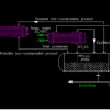
As I couldn't send the image in the discussion, I put the system as my profile picture.
So I see that the solution won't be much different than I imagined (profile photo), just connect the first condenser output nozzle to the second one.
Regarding the dry screw pump, its rotors are made of cast iron, and according to the safety data sheet, the gases are corrosive if they condense in the pump (a possible problem).
About the dry screw choice: we don't have considerable availability of steam in our unit, and in the case of liquid ring pumps, there is the problem of cavitation in vacuums lower than 15mmHg. I even considered LRP+atm air ejector, but at that moment I ended up recommending the dry screw.
Anyway, thank you very much.
Thanks
Thanks for the info Breizh, it was very helpful.
Follow the personal drawing
Regarding the system, this is exactly what I imagined Bobby, as part of the condensables can re-evaporate, making a vent outlet for another condenser (with cold water) between the vacuum pump and the reflux vessel. At the exit of the condenser of this cold water exchanger, there will be an immersion tube to return below the liquid height of the reflux vessel.
Also, I am considering a pressure equalization line between the reflux vessel and condenser 1
Thank you guys
Attached Files
-
 system.pdf 35.1KB
18 downloads
system.pdf 35.1KB
18 downloads
Edited by John Paulo Vieira, 14 May 2023 - 11:08 AM.
#7
-
- Admin
-
- 6,979 posts
Gold Member
Posted 13 May 2023 - 10:41 PM
Hi,
To add document, use the edit button (just underneath) then use full editor button then attach document.
Forget about the profile picture ,not visible.
Breizh
#8
-
- Members
-
- 3,529 posts
Gold Member
Posted 13 May 2023 - 10:42 PM
Your understanding seems faulty to me. I would use an elevated condenser with a dip leg into the reflux vessel and draw non-condensables from the condenser. And use a vent condenser draining into the reflux vessel via a dip leg. You seem to be flying blind. Learn to use the full editor to include drawings and such.
Bobby
#9
-
- Admin
-
- 6,979 posts
Gold Member
Posted 15 May 2023 - 10:28 PM
Hi,
It seems you don't understand the concept of barometric guard. Review the document from Graham and take into account the height of the barometric guard to cope with the vacuum required. You may have to relocate your distillate drum and/or the condensers.
Note: In any case you will have non condensable, inert from leaks and/or inert from the process which should be the base to design the capacity of the vacuum pump.
Breizh
Similar Topics

Organic Peroxide Distillation IssueStarted by Guest_Kimbreaux_* , 19 Feb 2026 |
|

|
||
Short Path Distillation Rotor SpeedStarted by Guest_MEC_* , 11 May 2023 |
|
|
||
Vacuum PumpStarted by Guest_R.t_* , 19 Sep 2025 |
|

|
||
Distillation Column Reboiler QuestionsStarted by Guest_AlanC079_* , 07 Jul 2025 |
|
|
||
Distillation Column Top PressureStarted by Guest_halkeshhulk_* , 27 Jun 2025 |
|
|

