 FB
FBChemical and Process Engineering Resources

Centrifugal Pumps: Basic Concepts of Operation, Maintenance, and Troubleshooting
Nov 08 2010 11:30 AM | Mukesh Sahdev in Fluid Flow
Working Mechanism of a Centrifugal Pump
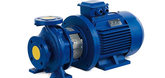
A centrifugal pump is one of the simplest pieces of equipment in any process plant. Its purpose is to convert energy of a prime mover (a electric motor or turbine) first into velocity or kinetic energy and then into pressure energy of a fluid that is being pumped.
The energy changes occur by virtue of two main parts of the pump, the impeller and the volute or diffuser. The impeller is the rotating part that converts driver energy into the kinetic energy. The volute or diffuser is the stationary part that converts the kinetic energy into pressure energy.
All of the forms of energy involved in a liquid flow system are expressed in terms of feet of liquid i.e. head.Generation of Centrifugal Force
 |
| Figure 1: Liquid Flow Path Inside a Centrifugal Pump |
The process liquid enters the suction nozzle and then into eye (center) of a revolving device known as an impeller. When the impeller rotates, it spins the liquid
Conversion of Kinetic Energy to Pressure Energy
The key idea is that the energy created by the centrifugal force is kinetic energy. The amount of energy given to the liquid is proportional to the velocity at the edge or vane tip of the impeller. The faster the impeller revolves or the bigger the impeller is, then the higher will be the velocity of the liquid at the vane tip and the greater the energy imparted to the liquid.
This kinetic energy of a liquid coming out of an impeller is harnessed by creating a resistance to the flow. The first resistance is created by the pump volute (casing) that catches the liquid and slows it down. In the discharge nozzle, the liquid further decelerates and its velocity is converted to pressure according to Bernoulli's principle.
Therefore, the head (pressure in terms of height of liquid) developed is approximately equal to the velocity energy at the periphery of the impeller expressed by the following well-known formula:
where: | Eq. 1 |

A handy formula for peripheral velocity is:
where: | Eq. 2 |

This head can also be calculated from the readings on the pressure gauges attached to the suction and discharge lines.
One fact that must always be remembered: A pump does not create pressure, it only provides flow.
Pressure is a just an indication of the amount of resistance to flow.
Pump curves relate flow rate and pressure (head) developed by the pump at different impeller sizes and rotational speeds. The centrifugal pump operation should conform to the pump curves supplied by the manufacturer. In order to read and understand the pump curves, it is very important to develop a clear understanding of the terms used in the curves. This topic will be covered later.
17 Comments
Very help to all of them.
I think in Equation 9, fiction loss should be subtracted rather than being added, to get NPSHa.
could anyone tell me about 'hunting in pumps'??
very very nice article , its clear all concept about Pumps
good to understand.
Nice Article. Very helpful.
Appreciate that you are sharing your knowledge in such a fine manner. The content is so well presented that its very easy to follow.
Best,
Mayuresh.
Thanks for the article. Is there a similar article about compressor, heaters, or operation of columns (i,e stripper/frac)?
Thanks