Chemical and Process Engineering Resources
Step One: Formation of Bubbles
To understand vaporization, two important points to remember are:
- We consider only the static pressure and not the total pressure when determining if the system pressure is less than or greater than the liquid vapor pressure. The total pressure is the sum of the static pressure and dynamic pressure (due to velocity).
- The terms pressure and head have different meanings and they should not be confused. As a convention in this article, the term "pressure" shall be used to understand the concept of cavitation whereas the term "head" shall be used in equations.
Thus, the key concept is - vapor bubbles form due to vaporization of the liquid being pumped when the local static pressure at any point inside the pump becomes equal to or less than the vapor pressure of the liquid at the pumping temperature.
The reduction in local static pressure at any point inside the pump can occur under two conditions:
- The actual pressure drop in the external suction system is greater than that considered during design. As a result, the pressure available at pump suction is not sufficiently high enough to overcome the design pressure drop inside the pump.
- The actual pressure drop inside the pump is greater than that considered during the pump design.
Pressure Reduction in the External Suction of the Pump
 |
| Figure 3: External Suction System |
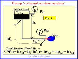
A simple sketch of a pump external suction system in shown in Figure 3. The nomenclature used for this figure is as follows:
ρ - Liquid density in lbm / ft3
G - Acceleration due to gravity in ft / s2
Psn - p refers to local static pressure (absolute). Subscript s refers to suction and subscript n refers to the point of measurement. The pressure at any point can be converted to the head term by division with the factor - ρ g
ps1 - Static pressure (absolute) of the suction vessel in psia
hps1 - Static pressure head i.e. absolute static pressure on the liquid surface in the suction vessel, converted to feet of head (ps1/ ρ g/gc). If the system is open, hps1 equals the atmospheric pressure head.
vs1 - Liquid velocity on the surface in the suction vessel in ft/s
hvs1 - Velocity head i.e. the energy of a liquid as a result of its motion at some velocity ‘vs1'. (v2s1 / 2g). It is the equivalent head in feet through which the liquid would have to fall to acquire the same velocity, or the head necessary to accelerate the liquid to velocity vs1. In a large suction vessel, the velocity head is practically zero and is typically ignored in calculations.
hs - Static suction head. . . . i.e. head resulting from elevation of the liquid relative to the pump centerline. If the liquid level is above pump centerline, hS is positive. If the liquid level is below pump centerline, hS is negative. A negative hS condition is commonly referred to as "suction lift".
hfs - Friction head i.e. the head required to overcome the resistance to flow in the pipe, valves and fittings between points A and B, inclusive of the entrance losses at the point of connection of suction piping to the suction vessel (point A in Figure 1). The friction head is dependent upon the size, condition and type of pipe, number and type of fittings, valves, flow rate and the nature of the liquid. The friction head varies as the square of the average velocity of the flowing fluid.
ps2 - Absolute static pressure at the suction flange in psia
hps2 - Static pressure head at the suction flange i.e. absolute pressure of the liquid at the suction flange, converted to feet of head - ps2 / ρ g/gc
vs2 - Velocity of the moving liquid at the suction flange in ft/s. The pump suction piping is sized such that the velocity at the suction remains low.
hvs2 - Velocity head at suction flange i.e. the energy of a liquid as a result of its motion at average velocity ‘vs2' equal to v2s2 / 2g.
pv - Absolute vapor pressure of the liquid at operating temperature in psia.
hpv - Vapor Pressure head i.e. absolute vapor pressure converted to feet of head (pv / ρ g/gc).
Hs - Total Suction Head available at the suction flange in ft.
Note: As pressure is measured in absolute, total head is also in absolute.
The pump takes suction from a vessel having a certain liquid level. The vessel can be pressurised (as shown in the Figure 3) or can be at atmospheric pressure or under vacuum.
Calculation of the Total Suction Head, Hs
The external suction system of the pump provides a certain amount of head at the suction flange. This is referred to as Total Suction Head (TSH), Hs.
TSH can be calculated by application of the energy balance. The incompressible liquid can have energy in the form of velocity, pressure or elevation. Energy in various forms is either added to or subtracted from the liquid as it passes through the suction piping. The head term in feet (or meters) is used as an expression of the energy of the liquid at any given point in the flow stream.
As shown in Figure 3, the total suction head, Hs, available at the suction flange is given by the equation,
| Hs = hps1 + hvs1 + hs - hfs + hvs2 | Eq. (8) |
For an existing system, Hs can also be calculated from the pressure gauge reading at pump suction flange,
| Hs = hps2 + hvs2 | Eq. (9) |
Equations8 and9 above include the velocity head terms hvs1 and hvs2, respectively.
Velocity Head
There is a lot of confusion as to whether the velocity head terms should be added or subtracted in the head calculations. To avoid any confusion remember the following:
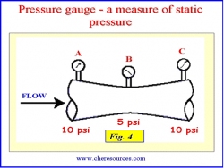
Just like a static tube of Pitot, a pressure gauge can measure only the static pressure at the point of connection. It does not measure the dynamic pressure as the opening of the gauge impulse pipe is parallel to the direction of flow and there is no velocity component perpendicular to its opening.
 |
| Figure 4: Measuing Static Pressure |
In Figure 4 below, flow through a pipe of varying cross section area is shown. As the cross section at point B reduces, the velocity of flow increases. The rise in kinetic energy happens at the expense of potential energy. Assuming that there are no friction losses, the total energy (sum of potential energy and kinetic energy) of fluid at point A, B and C remains constant. The pressure gauges at point A, B and C measure only the potential energy i.e. the static pressures at respective points. The drop in static pressure from 10 psi (point A) to 5 psi (point B') occurs owing to rise the dynamic pressure by 5 psi i.e. increase in velocity at point B. However the gauge at point B records only the static pressure. The velocity decreases from point B to C and the static pressure is recovered again to 10 psi.
At a particular point of flow, the total pressure is the sum of the static pressure and the dynamic pressure. Thus, theoretically, the velocity head terms must always be added and not subtracted, in calculating Total Suction Head (TSH), Hs. However, practically speaking, the value of these terms is not significant in comparison to the other terms in the equation.
- hvs1: In industrial scale suction vessels, the value of hvs1 is practically zero and it can be safely ignored.
- hvs2: It is good piping design practice to reduce the friction losses and prevent unnecessary flow turbulence by sizing the suction pipes for fluid velocities in the three to five feet per second range only. The velocity head corresponding to a velocity of 5 ft/s at the suction flange is only about 0.4 ft. Thus, for all practical purposes, in high head systems the velocity head at the suction flange is not significant and can be safely ignored. Only in low head systems does the factor need to be considered.
Therefore, neglecting the velocity head terms, Equations8 and9 simplify to:
| Hs = hps1 + hs - hfs | Eq. (10) |
Â
| Hs = hps2 | Eq. (11) |
Two important inferences can be drawn from the above equations:
- The pressure reduction in the external suction system is primarily due to frictional loss in the suction piping (Equation 10).
- For all practical purposes, the total head at the suction flange is the static pressure head at the suction flange (Equation 11).
Therefore the pump's external suction system should be designed such that the static pressure available at the suction flange is always positive and higher than the vapor pressure of the liquid at the pumping temperature.
For no vaporization at pump suction flange,
| (ps2 > pv) or (ps2 - pv ) or (hps2 - hpv ) > 0 | Eq. (12) |
As the liquid enters the pump, there is a further reduction in the static pressure. If the value of ps2 is not sufficiently higher than pv, at some point inside the pump the static pressure can reduce to the value of pv. In pumping terminology, the head difference term corresponding to Equation 5 (hps2 - hpv) is called the Net Positive Suction Head or NPSH. The NPSH term shall be explored in detail in the next part of the article. For now, the readers should focus only on how the static pressure within the pump may be reduced to a value lower than that of the liquid vapor pressure.
Pressure Reduction in the Internal Suction System of the Pump
The pressure of the fluid at the suction flange is further reduced inside the internal suction system of the pump.
 |  |
| Figure 5: Internal Pump Locations | Figure 6: Internal Pump Nomenclature |
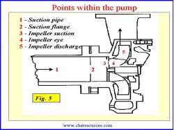
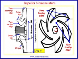
The internal suction system is comprised of the pump's suction nozzle and impeller. Figures 5 and 6 depict the internal parts in detail. A closer look at the graphic is a must in understanding the mechanism of pressure drop inside the pump.
In Figure 7, it can be seen that the passage from the suction flange (point 2) to the impeller suction zone (point 3) and to the impeller eye (point 4) acts like a venturi i.e. there is gradual reduction in the cross-section area.
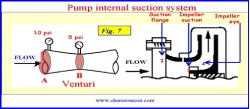 |
| Figure 7: Pump Internal Suction System |
In the impeller, the point of minimum radius (reye) with reference to pump centerline is referred to as the "eye" of the impeller (Figure 8).
According to Bernoulli's principle, when a constant amount of liquid moves through a path of decreasing cross-section area (as in a venturi), the velocity increases and the static pressure decreases. In other words, total system energy i.e. sum of the potential and kinetic energy, remains constant in a flowing system (neglecting friction). The gain in velocity occurs at the expense of pressure. At the point of minimum cross-section, the velocity is at a maximum and the static pressure is at a minimum.
The pressure at the suction flange, ps2 (Point 2) decreases as the liquid flows from the suction flange, through the suction nozzle and into the impeller eye. This decrease in pressure occurs not only due to the venturi effect but also due to the friction in the inlet passage. However, the pressure drop due to friction between the suction nozzle and the impeller eye is comparatively small for most pumps. However the pressure reduction due to the venturi effect is very significant as the velocity at the impeller increases to 15 to 20 ft/s. There is a further drop in pressure due to shock and turbulence as the liquid strikes and loads the edges of impeller vanes. The net effect of all the pressure drops is the creation of a very low-pressure area around the impeller eye and at the beginning of the trailing edge of the impeller vanes.
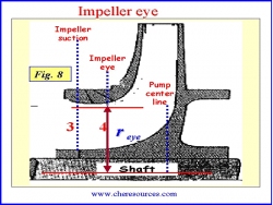 | 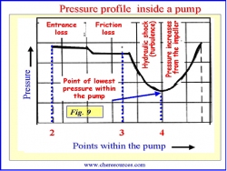 |
| Figure 8: Impeller Eye | Figure 9: Pressure Profile in a Pump |
The pressure reduction profile within the pump is depicted in Figure 9.
As shown in Figure 9, the impeller eye is the point where the static pressure is at a minimum, p4. During pump operation, if the local static pressure of the liquid at the lowest pressure becomes equal to or less than the vapor pressure (pv) of the liquid at the operating temperature, vaporization of the liquid (the formation of bubbles) begins i.e. when p4 <= pv.
It is at the beginning of the trailing edge of the vanes near the impeller eye where the pressure actually falls to below the liquid vapor pressure. The region of bubble formation is shown in Figure 10.
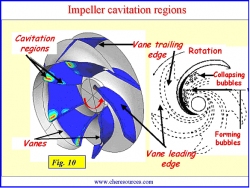 |
| Figure 10: Impeller Cavitation Regions |
In summary, vaporization of the liquid (bubble formation) occurs due to the reduction of the static pressure to a value below that of the liquid vapor pressure. The reduction of static pressure in the external suction system occurs mainly due to friction in suction piping. The reduction of static pressure in the internal suction system occurs mainly due to the rise in the velocity at the impeller eye.
Step Two: Growth of Bubbles
Unless there is no change in the operating conditions, new bubbles continue to form and old bubbles grow in size. The bubbles then get carried in the liquid as it flows from the impeller eye to the impeller exit tip along the vane trailing edge. Due to impeller rotating action, the bubbles attain very high velocity and eventually reach the regions of high pressure within the impeller where they start collapsing. The life cycle of a bubble has been estimated to be in the order of 0.003 seconds.
Step Three: Collapse of Bubbles
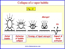 |
| Figure 11: Collapse of Vapor Bubbles |
As the vapor bubbles move along the impeller vanes, the pressure around the bubbles begins to increase until a point is reached where the pressure on the outside of the bubble is greater than the pressure inside the bubble. The bubble collapses. The process is not an explosion but rather an implosion (inward bursting). Hundreds of bubbles collapse at approximately the same point on each impeller vane. Bubbles collapse non-symmetrically such that the surrounding liquid rushes to fill the void forming a liquid microjet. The micro jet subsequently ruptures the bubble with such force that a hammering action occurs.Bubble collapse pressures greater than 1 GPa (145x106 psi) have been reported. The highly localized hammering effect can pit the pump impeller. The pitting effect is illustrated schematically in Figure 11.
After the bubble collapses, a shock wave emanates outward from the point of collapse. This shock wave is what we actually hear and what we call "cavitation". The implosion of bubbles and emanation of shock waves (red color) is shown in a small video clip shown below.
In nutshell, the mechanism of cavitation is all about formation, growth and collapse of bubbles inside the liquid being pumped. But how can the knowledge of mechanism of cavitation can really help in troubleshooting a cavitation problem. The concept of mechanism can help in identifying the type of bubbles and the cause of their formation and collapse. The troubleshooting method shall be explored in detail in the next part of the article.
Next let us explore the general symptoms of cavitation and its affects on pump performance.
| Video: Cavitation in a Centrifugal Pump |

 FB
FB


12 Comments
Great article but in your classification of pump problems, you have left out the most important class., i.e. problems in getting required parameters because of system conditions.Design Problems is of little use to the site engineer as he can't do anything about it. He can definitely correct system problems however.
Hii
I have a question regarding centrifugal pump.
A new pump is under commssioning in my plant and we have to go for water trial, can you please provide details on that how to proceed?
Great... thank u,,,,
THE BEST ONE...........
Thanks a lot ; it is much better than any other text about this topic in the pump literature , thanks again