FB
FB


Problem:
- Two Pumps are installed in field. 01 Duty and 01 Spare
- During pump change-over, cavitation problem occurs.
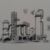
- It is proposed from client that install equalization line from pump casing vent and return line back to suction vessel as per sketch in blue color.
- Unfortunately in field, no casing vent connection is available.
- Pump is designed for -0.5 Barg suction pressure.
QUESTIONS
- How this equalization line works?
- After pump start-up, equalization line will be Closed or normally open?
- As no casing vent is available, so where this line shall be installed? i.e. on Suction side or Discharge side.
- What would be the RO sizing criteria? Flow and Pressure drop across RO.
Attached Files
-
 Equalization.GIF 45.42KB
51 downloads
Equalization.GIF 45.42KB
51 downloads