Jump to content


Photo * * * * - 4 votes

Liquid Pipeline Surge


Liquid Pipeline Surge Pipeline Surge has been a hotly debated topic on "Cheresources". During one of these discussions I had said that I would try to compile a blog entry related to pipeline surge possibly with an excel workbook. Today's blog entry discusses pipeline surge sans the excel workbook. I expect the young process engineers to develop their own spreadsheet from this blog entry. What I am going to discuss is the fundamentals related to pipeline surge which also form part of the excel workbook I created for pipeline surge, as explanatory notes on the phenomena of surge. Let us begin:

Pressure Surges:
- Pressure surges in a pipeline are created by a change in momentum of the moving stream, e.g. by closing a valve, the origin of the pressure surge being at the point where the momentum of flow is changed.

- Because of the low density of gases compared to liquids, pressure surges are not of concern in gas lines.

- The theoretical maximum pressure surge that can be created in a pipeline would be caused by an instantaneous total blockage of the flow and would occur at the point of flow retardation, e.g. the valve.

- The maximum surge pressure is the sum of two components:
(i) The instantaneous pressure increase at the moment of total flow blockage
(ii) The subsequent gradual pressure rise due to the 'line packing' effect.

The magnitude of the instantaneous surge can be calculated using Joukowsky's equation:

Ps = ρ*a*Δv

where:

Ps = surge pressure, Pa
ρ = liquid density, kg/m3
a = pressure wave velocity, m/s
Δv = velocity change, m/s

The wave velocity "a" is given by:

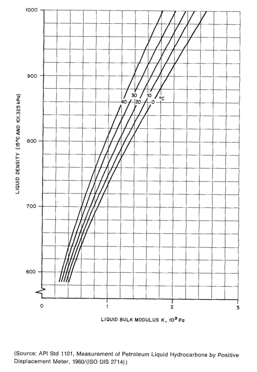
a = square root(1 / ((1/K + (d/tw)*(1/E))*ρ))

where:

K = Liquid Bulk Modulus (refer attachment); water bulk modulus is generally considered as 2.2*109 Pa
d = pipe internal diameter, m
tw = pipe wall thickness, m
E = Young's modulus of pipe material, Pa (for commercial steel it is considered as 210*109 Pa)

Methods of Reducing Surge Pressure:
The primary method of preventing the generation of unacceptably high surge pressures should be the implementation and strict adherence to well formulated and clearly written operating procedures. Additional measures which may be employed to reduce surge pressures are as follows:

1. Slow Valve Closure:
By closing a valve over a sufficiently long period the surge generated may be significantly reduced. This also allows more time to trip the pumps and hence reduce the maximum pressure. This can be implemented either by slowing down the valve actuator or by installing a two speed actuator which reduces the valve closure speed over the (critical) last 10-20% of the valve's travel.

2. Installing a Pressure Relief System:
If the creation of an unacceptable pressure surge cannot be avoided using option 1, a pressure relief system can be installed as near to the point of surge origin as practically possible. The system would vent a quantity of product from the pipeline once a pre-set pressure limit is exceeded thereby limiting the final surge pressure. This can be implemented using bursting discs or rapid response relief valves.

3. Installing a Pump Trip:
If the advent of a potentially dangerous pressure surge is detected early enough, the tripping of the upstream pumps will generate a negative pressure wave which propagates from the pumps to the origin of the surge and can counter the positive pressure surge. The effectiveness of this form of surge protection depends on factors such as the pipeline length, amount of line packing, etc.

Readers of my blog, hope you enjoy this blog entry and I look forward to your comments.

Regards,
Ankur.

Attached Thumbnails

  • Attached Image


Hi Ankur , thanks for the posts , We recenly came across a problem where the client reported a  damaged Angle Stop check valve next to the Pump  due to Surge pressure. According to the client  when the Client Stopped one of the pumps & started the Other ( 1 working & 1 std by pump) , the Angle Stop check valve next to the Pump which was stopped got damaged . According to him it was due to surge pressure . The Total pipe length is about 40 metres from the Discharge point and the valve. Is there any solution that we can adopt to mitigate this problem ?

Please advise

Install a rapid response relief valve or Rupture Disk downstream of the angle stop valve to mitigate this problem.


Another way of mitigating this problem would be to provide non-slam check valves at the pump discharge to prevent damage due to pressure surge. Some links are provided below: 


http://www.eng-tips.....cfm?qid=336042


http://www.eng-tips.....cfm?qid=111189


http://www.valmatic....heckvalves.html


Hope this helps.


Regards,

Ankur


Zatish,

Incremental increase in pressure with incremental closing of a valve cannot be provided as a simple mathematical equation. This would lnvolve complex equations and thousands of iterations over the incremental valve closure to predict the pressure profile as the valve closes. In a nutshell, the whole calculation for valve closure as a function of time and the corresponding pressure rise can be classified as transient or dynamic modeling of the surge process and better be done using a pipeline transient simulation software such as TLNET / TGNET or OLGA.

You can put in a separate post wher you can upload the surge volume calcualtion file.

Regards,
Ankur.

Dear Ankur,
But all simulation programs starts with mathematical model and all model starts with mathematical equations.
Base line of simulation is still the same.
Number of unknown= Number of equations.
I could not upload file for another member.
If you can help with steps please.........
Thanks and Regards


Hello Sir, i am also strugling to find the solution of one of the transient problem. Details of problem is as follows.....

i am having a pump which is designed to supply kerosene at required pressure to a storage tank. The inlet of pump is 20bar.  Due to safety reasons actual supply reserviour is located far away from the pump inlet. since the supply reserviour is located away from the pump inlet, pressure drop in the line is of the order of 10bar. So to reduce the variation in pressure in the begining, one more starting supply reserviour is located vey close to pump inlet. To reduce the variation in pressure at inlet of pump kerosene will be fed to the pump inlet by the second starting supply reserviour just for few second. once the steady state is achieved, flow is switched to actual supply reserviour by means of Electro Pneumatic ball valves. My question is how to proceed or calculate the surge(if any) in pressure due to this valve switchover behaviour.


Thanks in advance

Hi...ankur

i am also having a problem related with transient flow behaviour.....deilas are as listed below.

i am having a pump which is designed to supply kerosene at required pressure to a storage tank. The inlet of pump is 20bar.  Due to safety reasons actual supply reserviour is located far away from the pump inlet. since the supply reserviour is located away from the pump inlet, pressure drop in the line is of the order of 10bar. So to reduce the variation in pressure in begining, one more starting supply reserviour is provided close to pump inlet. To reduce the variation in pressure at inlet of pump kerosene will be fed to the pump inlet by the second starting supply reserviour just for few second. once the steady state is achieved, flow is switched to actual supply reserviour by means of Electro Pneumatic ball valves. My question is how to proceed or calculate the surge(if any) in pressure due to this valve switchover behaviour.

As a solution to surge on suction side of pump, can we put a Pressure Control valve at the suction side of the pump to avoid suction side surges? suction side surges could be due to the pump or due to other users (pumps stations) in the supply network...

engg,


I have never heard of surge in suction line of pump. Suction lines are generally short and velocities are low and hence suction lines shouldn't be seeing surge.


Vibrations in suction line of reciprocating pumps is something which is a known phenomena and there are various means to control it.


I also have never encountered a pressure control valve in a pump suction line. Sizing criteria of pump suction lines is to minimize pressure drop in them in order to achieve as high as possible a "Net Positive Suction Head".


I guess you need to elaborate further for any further understanding on my part.


Regards,

Ankur

The Joukowsky equ. is applicable for mainly in simple linear piping systems where no branches by which waves can be reflected back and cause constructive interference in the main line. Joukowsky equ. does not consider Column separation and consideres instant valve closure. So, some limitations by using joukowsky equ.

To answer to the question above on closure of Electro Pneumatic ball valves, first, must do a complete model using transient software i.e Stoner, AFT Impulse etc.. then all proper equipment data to be implemented in the input file i.e valve sizes CVs closing/opening times, pump curves all that jazz then a control system to be implemented to simulate the switch over when flow is diverted. You may have to input separate timings for valve activation for the corresponding flow rates

Hi Akur,


It's been decades that we've not communicated and hopefully you're still around in this time of Pandemic.


I'll appreciate if you could still send me "Pressure Drop Calculation Spreadsheet". I got lost of that copy a long time ago. I found it very simple & useful.


You can send it to my email at bert_abarilla@yahoo.com


Many thanks & wish you good health & your family.


Roberto

Latest Visitors

  • Photo
    daraj
    Today, 04:24 AM
  • Photo
    hilman01
    Today, 01:15 AM
  • Photo
    newtonslaw
    Yesterday, 02:58 PM
  • Photo
    Cramirez
    Yesterday, 09:21 AM
  • Photo
    Shashank JS
    Yesterday, 05:29 AM
  • Photo
    Platonicus
    Yesterday, 12:25 AM
  • Photo
    anirudhan86
    26 Mar 2024 - 23:08
  • Photo
    UrosBozovic
    26 Mar 2024 - 18:09
  • Photo
    yusifsam95
    26 Mar 2024 - 11:30