 FB
FB
 3 votes
Multiple Centrifugal Pumps In Series And Parallel
14 December 2012
 For many young process engineers the concept of multiple centrifugal pumps in series or parallel is often confusing. Today's blog entry tries to explain the concept of centrifugal pumps in series and parallel.
First of all let us understand what it means by pumps in series and parallel.
When we say multiple pumps are in series, it means that the discharge of the first pump provides the suction to the second pump and the discharge of the second pump provides the suction to the third pump and so on and so forth depending on the number of pumps in series.
When we say multiple pumps are in parallel, the flow to the suction is split depending on the number of pumps in parallel and when the individual discharge connections from the individual pumps in parallel unite to form a common discharge pipe or discharge header the flow recombines as a summation of the individual pump flows.
Let us try to understand the concept of series and parallel in terms of the flow Q and head H for the pumps.
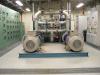
To begin with let us start with pumps in series. In a series arrangement, each pump handles the same flow rate, but the total head produced by the combination of pumps will be additive. Since each pump generates a head H corresponding to a flow Q, when configured in series, the total head developed is HT = H1 + H2, where H1, H2 are the heads developed by the pumps in series at the common flow rate Q. This is illustrated in the attached sketch 1, where pump A produces a head H1 at a capacity of Q, while Pump B produces a head of H2 at the same capacity Q. Being in series, the combined head is the sum of the two heads.
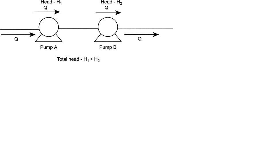
The attached sketch 2 shows the single pump head curve and the combined head curve for two identical pumps in series. Each pump produces a head of H = 1200 at a capacity of Q = 1000 gpm. The combination in series will generate a total head of HT = 2400 at a capacity of Q = 1000.
Suppose there are three identical pumps in series, each producing 1500 ft of head at 1000 gpm capacity. The total head generated by the three pumps in series at 1000 gpm is:
HT = 3*1500 = 4500 ft
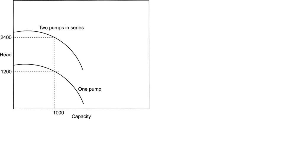
If these pumps in series are not identical but instead have differing heads of 1500 ft, 1200 ft, and 1400 ft at 1000 gpm, as shown in attached sketch 3, the total head generated by these pumps in series at Q = 1000 gpm is:
HT = 1500 + 1200 + 1400 = 4100 ft
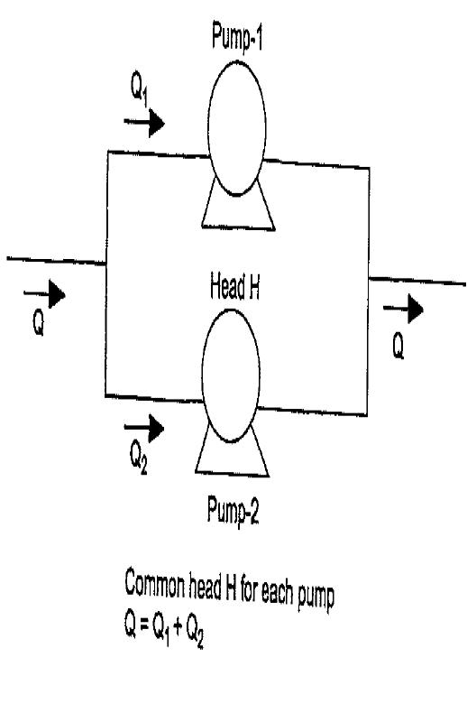
Let us now move on to pumps in parallel. As mentioned earlier, for pumps configured in parallel, the flow rate Q is split between the pumps at the inlet into Q1 and Q2 and after passing through the pumps on the discharge side, the flows recombine back to the flow rate of Q, as shown in attached sketch 4. Each pump develops the same head H at the corresponding capacity. Thus, the first pump at capacity Q1 develops the same head H as the second pump at capacity Q2. This commonality of head across parallel pumps is the most important feature of pumps installed in parallel. If the pump heads are not matched, pumps in parallel will not function properly.
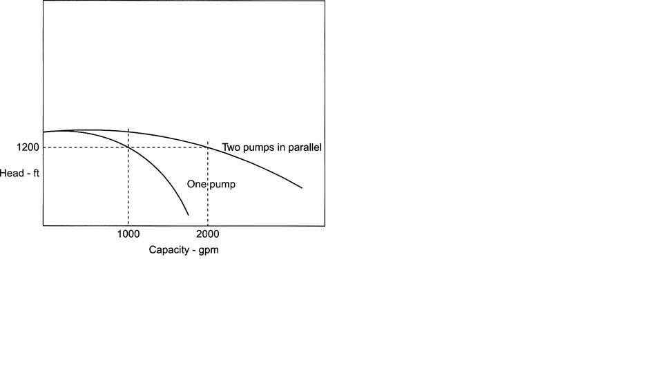
Consider two identical pumps, each with the H-Q curve, as shown in sketch 5. The combined H-Q curve in parallel operation is labeled in the figure as two pumps in parallel. At a head of 1200 ft, the capacity of each pump is 1000 gpm. Therefore, in combination, the parallel pumps will be capable of pumping 2000 gpm, generating a common head of 1200 ft. Every point on the combined H-Q curve has a capacity double that of each pump at the same head.
Therefore, when installed in parallel, the flow rates are additive, while the head across each pump is the same. Suppose there are three identical pumps, each developing 800-ft head at a capacity of 400 gpm. When configured in parallel, the flow rate of 1200 gpm is split equally through each pump (400 gpm each), and each pump develops a head of 800 ft. Thus, the total flow is:
QT = 400 + 400 + 400=1200 gpm
And the common head across each pump is H1 = H2 = H3 = 800 ft
To conclude, pumps in series have a common flow rate with heads being additive. With pumps in parallel, the flow rates are additive with a common head.
Hope the readers of my blog like this brief explanation on behavior of centrifugal pumps in series and parallel.
Let me have your opinion in the form of comments on this blog entry.
Regards,
Ankur.
Reference: Working Guide to Pumps and Pumping Stations - Calculations and Simulations by E. Shashi Menon and Pramila S. Menon


Dear Mr. Ankur,
This is a very good article.
I have query in positive displacement pumps. This forum is for centrifugal pumps. My apology if I am diverting the topic.
What will be the head and flow characterstics in case of two screw pumps/Gear pumps are in parallel ?
This scenario happens in the lube oil skid of compressor. During changeover, the main lube oil pump and Auxilliary lube oil pumps run simultaneously in parallel. What will be change in overall discharge pressure and flow charcterstics.