 FB
FB
 1 votes
Pressure Drop Of Pseudo-Plastic Fluids In Pipes
14 November 2013
 Dear All,
Pseudo-plastic fluids are a type of non-newtonian fluids and account for a majority of the non-newtonian fluids commonly found in the chemical process industry and specifically in the food processing industry.
Today's blog entry provides a methodology to calculate the pressure drop of a pseudo-plastic fluid in a pipe. An example problem is solved at the end of the outlined method. Readers can use the example problem to develop a spreadsheet based calculation
For Pseudo-plastic non-newtonian fluids, the power law model is used to define the shear stress versus velocity gradient relationship. The power law equation is as follows:
τ = K*(dV/dy)n
where:
τ = shear stress at distance y from pipe wall
K = flow consistency index
dV/dy = velocity gradient or shear rate
n = flow behavior index
For pseudo-plastic fluids n < 1, and for dilatant fluids n > 1. Since the apparent viscosity μ is the slope of the shear stress τ versus velocity gradient plot, we can calculate the apparent viscosity of a non-newtonian fluid that follows the power law from the following equation
µ =K*(dV/dy)n-1
or
K = 0.001*µ*(dV/dy)1-n
where:
µ = Apparent Viscosity, cP
K = Flow consistency index, Pa.sn
dV/dy = velocity gradient, s-1
n = flow behavior index, dimensionless
Power-Law Reynolds Number:
RePL = 23-n*(n / (3n+1))n*((V2-n*Dn*ρ) / K)
where:
RePL = Power-Law Reynolds Number, dimensionless
V = Velocity of flow in pipe, m/s
D = Inside diameter of pipe, m
ρ = density of the fluid, kg/m3
Determining fanning friction factor 'f' for laminar flow of power-law fluids:
f = 16 / RePL
where:
f = fanning friction factor, dimensionless
Note:
The transition from Laminar to Turbulent flow for pseudo-plastic fluids is considered at a Reynolds number of 2100.
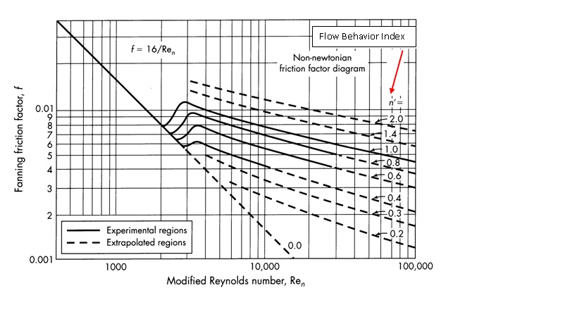
Determining fanning friction factor 'f' for turbulent flow of power-law fluids:
Refer attached chart
Friction Loss (in head) using Fanning friction factor:
hf = 2*f*V2*L / (g*d)
where:
hf = friction loss (in head) in the pipe, m (meters of liquid column)
L = Length of the pipe, m
g = Acceleration due to gravity, 9.81 m/s2
Example Problem:
A coal slurry is to be transported by horizontal pipeline. It has been determined that the slurry may be described by the power law model with a flow behavior index of 0.4, an apparent viscosity of 50 cP at a shear rate of 100 /s, and a density of 1442 kg/m3. What would be the pressure drop and the horsepower (HP) required to pump the slurry at a rate of 0.06 m3/s through an 8 in. Schedule 40 pipe that is 80 km long ?
Inputs:
n = 0.4
µ = 50 cP
dV/dy = 100 s-1
ρ = 1442 kg/m3
D = 0.202 m (based on nominal pipe size in inches and Pipe schedule)
L = 80 km
Q = 0.06 m3/s
Results:
L = 80,000 m
K = 0.792 Pa.sn
V = 1.87 m/s
RePL = 8025
f = 0.0048 (from chart)
hf = 1358 m
ΔP = 192 bar
HP = 1153038 W = 1153 kW
Hope all of you have found this blog entry very informative. I look forward to comments from the readers of my blog.
Regards,
Ankur.


Dear Sir
I have problem for size of the Pipe and My Problem is
Line Size is 19 dia (OD) Seamless pipe SS 316L (1.6 thick.)
Pressure Is 30 Bar@40 oC
Fluid Just Like a Water
Without Assumed Velocity
Find Out Velocity in the Pipe Or Flow Rate in the Pipe
Regarding the Subject to any Formula or Excel sheet Please shared with my personal mail ID tarang.suthar@gmail.com