 FB
FB
 1 votes
Pressure Drop In Fixed (Single Phase Tubular Packed) Bed Reactors
29 July 2015
 Dear All,
Today's blog entry relates to pressure drop in fixed bed reactors.
Let us examine the components that contribute to the calculated pressure drop in fixed bed reactors. The design pressure drop should consider a safety margin on the calculated pressure drop.
Bed Pressure Drop: For both gases and liquids this should be calculated based on the "Ergun" equation given as:
(ΔP/L) = K*Re*(150 + 1.75*Re)*((1 – ε) / ε)^3*(µ^2 / (ρ*Dp^3))
where:
(ΔP/L) = pressure drop kPa/m (psi/ft) of bed
Re = Reynolds number, dimensionless = W*Dp/(µ*(1 - ε))
ε = Void fraction of bed, dimensionless
µ = viscosity of gas or liquid at conditions, Kg/m.s (lb/ft.hr)
K = Dimensional constant = 0.001 (Metric) = 1.665E-11 (USC)
ρ = gas or liquid density at conditions, kg/m3 (lb/ft3)
Dp= Equivalent particle diameter, m (ft)
W = mass flux of gas or liquid, kg/s.m2 (lb/hr.ft2) based on reactor cross-sectional area
The equivalent particle diameter to be used in pressure drop calculations for cylindrical shapes is given by the following:
Dp = 3*D*L / (2*L + D)
where:
Dp = Equivalent particle diameter, m (ft)
D = Actual particle diameter, m (ft)
L = Average particle length, m (ft)
The "Ergun" constants of 150 and 1.75 have been given by fitting pressure drop data from a wide variety of particle systems. Use of the equation and these constants for a given unique shaped particle can sometimes result in significant error in the pressure drop prediction. In addition, error is often introduced into the pressure drop calculation through the estimate of bed voidage and the equivalent particle diameter. These errors are caused due to uncertainty in the particle density and particle dimensions.
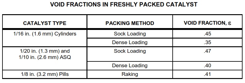
Sock Loading: Prior to the 1970s, the standard method for loading catalyst in a fixed bed reactor was sock loading. In sock loading, a canvas tube conveys the catalyst from the reactor inlet manway to the bottom of the reactor catalyst bed. The sock is attached to a loading hopper or funnel at the reactor inlet, which discharges the catalyst through the sock upon the bed surface in a manner which prevents the individual particle (specifically cylinders) from finding a stable, horizontal rest position. The cylinders stack in various horizontal and vertical positions.
The positioning of catalyst cylinders in random orientations encourages bridging of cylinders and void spaces between cylinders. During reactor operations, these bridges and void spaces tend to collapse. Bed density then increases as the bed depth shrinks.
Dense Loading: Since 1970, refiners, catalyst manufacturers, and catalyst-loading contractors have developed dense-loading devices that dramatically reduce void spaces and bridging. Dense loading can increase catalyst bed densities by as much as 17%.
Moreover, unlike sock loading, dense loading does not require personnel inside the reactor to distribute the catalyst evenly from the sock. Workers inside the reactor require breathing air and weight distribution shoes to prevent crushing of the catalyst underneath their weight.
Dense loading is accomplished by introducing the catalyst particles (specifically cylinders) into the reactor in a manner that allows each cylinder to fall freely to the catalyst surface. Individual cylinders separately assume a horizontal rest position before being impinged by other cylinders. Under this regime, cylinders tend to pack horizontally, minimizing the possibility of bridging or creating void spaces.
Bed Lifting Pressure Drop: For the less frequently encountered upflow operation in a reactor, the calculated pressure drop from the above equation must be kept below the theoretical bed lifting pressure drop, preferably less than 50% and in no case more than 75%. The bed lifting theoretical pressure drop is given by:
(ΔP/L)BL = K*(ρp – ρ)*(1 – ε)
where:
(ΔP/L)BL = Theoretical Bed Lifting Pressure Drop of bed, kPa/m (psi/ft)
ρp = particle density of catalyst, kg/m3 (lb/ft3)
ρ = Density of gas or liquid at conditions, kg/m3 (lb/ft3)
ε = Void fraction of bed, dimensionless
K = Dimensional constant = 0.0098 (Metric) = 0.00694 (USC)
Inlet Nozzle Pressure Drop: Pressure drop through the inlet nozzle is the sum of the following terms represented in equation form:
ΔPe = (K*ρ*(UL – UI)^2) / 2
ΔPi = (1.3*K*ρ*UI^2) / 2
ΔPb = (0.5*K*ρ*UL^2) / 2
where:
ΔPe = pressure loss due to sudden expansion from line to expanded section of inlet distributor, kPa (psi)
ΔPi = pressure drop due to impingement of the gas in the bottom plate or dish of the inlet distributor, kPa (psi)
ΔPb = pressure drop through the slots of the inlet distributor, kPa (psi)
ρ = Density of gas or liquid at conditions, kg/m3 (lb/ft3)
UI = velocity in expanded section of inlet distributor, m/s (ft/sec)
UL = velocity in external piping, m/s (ft/sec)
K = Dimensional constant = 0.001 (Metric) = 2.156E-4 (USC)
Collector and Outlet Nozzle Pressure Drop: Pressure drop through the collector and outlet nozzle is the sum of the following terms represented in equation form:
ΔPs = (2.8*K*ρ*US^2) / 2
ΔPc = (0.5*K*ρ*UL^2) / 2
where:
ΔPs = Pressure drop through holes and slots of collectors, kPa (psi)
ΔPc = Pressure drop due to sudden contraction at entrance to the outlet nozzle, kPa (psi)
US = velocity through holes and slots, m/s (ft/sec)
K = Dimensional constant = 0.001 (Metric) = 2.156E-4 (USC)
This is all for today's blog entry and I look forward to comments from the reader's of my blog.
Regards,
Ankur.


