Jump to content


Featured Articles

Check out the latest featured articles.

File Library

Check out the latest downloads available in the File Library.

New Article

Product Viscosity vs. Shear

Featured File

Vertical Tank Selection

New Blog Entry

Low Flow in Pipes- posted in Ankur's blog

- - - - -

Reboiler Vaporization Calculation

column relief reboiler duty

This topic has been archived. This means that you cannot reply to this topic.
16 replies to this topic
Share this topic:
| More

#1 Arpit_Jain

Arpit_Jain

    Veteran Member

  • Members
  • 46 posts

Posted 23 June 2013 - 09:22 AM

Dear Experts,

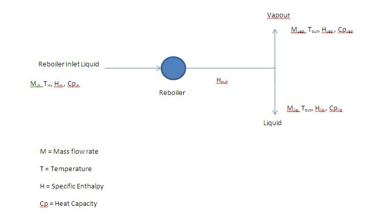
For relief load calculation, I need to know amount of reboiler duty getting used in vaporizing the liquid.

For that I am following two approaches:

Approach 1: Multiplying the difference in specific enthalpy of reboiler outlet vapor stream and reboiler inlet liquid steam with the mass flow rate of reboiler outlet vapor stream.

Approach 2: Calculating the amount of heat going in the reboiler outlet liquid stream using MCpΔT method, where M is the reboiler outlet liquid stream flow rate, Cp is the average Cp of reboiler inlet liquid and reboiler outlet liquid and ΔT is the temperature difference in the reboiler inlet and outlet stream.

Both the approaches are giving different results.

It seems that the error in approach 1 might be due to composition difference between reboiler inlet liquid and outlet vapor. (Not sure about it).

Could you please help me in finding the right approach and suggest the conceptual mistake that I am making here?

Thanks in advance !!
 

Regards,

Arpit Jain


#2 Bobby Strain

Bobby Strain

    Gold Member

  • Members
  • 3,529 posts

Posted 23 June 2013 - 11:00 AM

It seems that your whole approach is wrong. You need to perform a heat balance and material balance for the entire column. Search a bit to find the proper procedure.


Bobby


#3 S.R.Shah

S.R.Shah

    Gold Member

  • Members
  • 113 posts

Posted 23 June 2013 - 11:11 AM

Simple approach is to calculate heat duty of utility.suppose thermic liquid is used to heat and vaporize process liquid ;use m x cp x del t. Plz. Consider heat loss at reboiler surface. This shall give you more exact data.

If you would like to calculate reboiler duty on process side;overall energy balance of system is required

#4 Arpit_Jain

Arpit_Jain

    Veteran Member

  • Members
  • 46 posts

Posted 23 June 2013 - 12:22 PM

You seem to have understood my question wrongly.


I wish to know the distribution of reboiler duty in vapour phase and liquid phase separately for the reboiler outlet stream. (# amount of reboiler duty getting used in vaporizing the liquid.)


Edited by Arpit_Jain, 23 June 2013 - 12:24 PM.


#5 ankur2061

ankur2061

    Gold Member

  • Forum Moderator
  • 2,484 posts

Posted 23 June 2013 - 01:18 PM

Arpit,


Refer page 10 of the attachment. This is a lecture on Reboiler Circuit Design from University of Haifa.


Regards,

Ankur.

Attached Files


#6 Arpit_Jain

Arpit_Jain

    Veteran Member

  • Members
  • 46 posts

Posted 23 June 2013 - 11:30 PM

Thank you sir for help.


But I am not looking for a different thing. I am sorry if there is some language error in my query posted that might be creating confusion.

Let me explain the question in different way:


I know the reboiler duty of the column. I need to know what part of heat is going in the sensible heat and what part is going in the latent heat for vaporizing. 


Attached is the flowsheet of reboiler showing inlet stream and outlet vapor and liquid stream.

Capture.JPG


Methods for calculation of duty used in vapour generation (Qreq):

Approach 1: Multiplying the difference in specific enthalpy of outlet vapour and reboiler inlet liquid by the outlet vapour mass flow rate,


Qreq  =  [(Hout - Hin) * Min] – [(Hliq – Hin) * Mliq]                                                                                         … (i)

Or,  Qreq  =  [(Hout - Hin) * Min] – Qliq                                                                                                                                          … (ii)


Approach 2: Calculating the heat taken away by the outlet liquid and then subtracting it from reboiler duty.


Qliq = Mliq * Cpavg * ∆T                                                                                                                            … (iii)

Where, Cpavg = (Cpin + Cpliq)/2 and ∆T = Tout – Tin

Qreq =  (Hout - Hin) * Mvap – Qliq


Comparing (i), (ii) and (iii) we show that

(Hliq – Hin) ≈ Cpavg * ∆T


When comparing the results of these 2 approaches for a simulation model, a mismatch is found in the value of Qreq.


Please suggest me if I am committing any conceptual mistake. Also, please inform me in case you need more details.


Thanking you.


Regards,

Arpit


#7 Arpit_Jain

Arpit_Jain

    Veteran Member

  • Members
  • 46 posts

Posted 24 June 2013 - 12:19 AM

One more approach can be to flash the reboiler outlet stream and then bringing the liquid portion of reboiler outlet to original  pressure and temperature using simulation software and calculating the resultant duty. This will give the sensible heat going in the liquid portion of the outlet stream.


Is this approach correct ?


#8 Art Montemayor

Art Montemayor

    Gold Member

  • Admin
  • 5,780 posts

Posted 24 June 2013 - 06:47 AM

Arpit:


There is confusion in this thread because of what you are proposing (and not explaining):

  • A "reboiler" is used in a distillation column to actually boil again the saturated liquid fed to it by the trays above it in the distillation column.  That is why it is called a "reboiler".  That is the normal, conventional method for carrying out a distillation.
  • Note that the liquid normally fed to the reboiler is SATURATED.  it has to be saturated since the basic assumption in a distillation operation is that every tray has saturated liquid in order to carry out a differential distillation from tray to tray through differential temperature gradients.
  • If the liquid fed to the reboiler is saturated, where do you come up with sensible heat being required for the reboiler?  Your sketch is nothing more than a quick drawing of a heat exchanger, not a reboiler.   Show how your reboiler is hooked up to its column.  This is probably what is confusing everyone.
  • Show how you are feeding a mixture directly into the reboiler, and not into the distillation column trays.
  • Also explain why you can't figure out the sensible part of the feed to the reboiler.

Then, perhaps, our members will have a better conception of what you are proposing.


#9 srfish

srfish

    Gold Member

  • ChE Plus Subscriber
  • 408 posts

Posted 24 June 2013 - 09:26 AM

For accuracy I would not work with average specific heats. Use the molecular weight of the vaporizing fluid and it's latent heat  to determine the latent heat duty. Then subtract that heat duty from the overall heat duty to obtain the sensible heat duty.


#10 sheiko

sheiko

    Gold Member

  • ChE Plus Subscriber
  • 732 posts

Posted 24 June 2013 - 11:04 AM

Hi Arpit,
The overall heat duty is the sum of:
- sensible heat to change temperature of liquid from inlet temp to outlet liquid temp
- sensible heat to change temperature of vapor from inlet temp to vapor temp
- latent heat to vaporize liquid at reboiler pressure
As you have all required flowrates, temperatures, heat capacities, reboiler (or tower bottom) pressure and latent heat, it should be simple.
Regards.


Edited by sheiko, 07 October 2013 - 05:00 AM.


#11 Arpit_Jain

Arpit_Jain

    Veteran Member

  • Members
  • 46 posts

Posted 24 June 2013 - 01:54 PM

  • Note that the liquid normally fed to the reboiler is SATURATED.  it has to be saturated since the basic assumption in a distillation operation is that every tray has saturated liquid in order to carry out a differential distillation from tray to tray through differential temperature gradients.
  • If the liquid fed to the reboiler is saturated, where do you come up with sensible heat being required for the reboiler?  Your sketch is nothing more than a quick drawing of a heat exchanger, not a reboiler.   Show how your reboiler is hooked up to its column.  This is probably what is confusing everyone.


Dear Mr. Art,


Yes, the feed to the reboiler will be saturated as it will be at its bubble point temperature. By sensible and latent heat I mean exactly what explained by Mr. Sheiko i.e.

- sensible heat: heat given to change temperature of liquid from inlet temp to outlet liquid temp
- sensible heat: heat given to change temperature of vapor from inlet temp to vapor temp
- latent heat: heat given to vaporize liquid at reboiler pressure


And yes the feed is column bottom and my reboiler is once through.


Hi Arpit,
The overall heat duty is the sum of:
- sensible heat to change temperature of liquid from inlet temp to outlet liquid temp
- sensible heat to change temperature of vapor from inlet temp to vapor temp
- latent heat to vaporize liquid at reboiler pressure
As you have all requires flowrates, temperatures, heat capacities, reboiler (or tower bottom) pressure and latent heat, it should be simple.
Regards.


Dear Mr. Sheiko,

As all these inputs are available calculation is simple. But the problem I am facing is that all the 3 approaches that I mentioned above seem to be correct to me. But there is a mismatch in the result.  (Approach 1 is followed by a licensor company).

The approach that I undersand is the most appropriate is approach 3 i.e.

To flash the reboiler outlet stream and then bringing the liquid portion of reboiler outlet to original  pressure and temperature using simulation software and calculating the resultant duty. This will give the sensible heat going in the liquid portion of the outlet stream

I want to confirm its correctness as I am using this duty for relief load calculation (unbalanced heat load method) in the scenario where feed to column has stopped.


For accuracy I would not work with average specific heats. Use the molecular weight of the vaporizing fluid and it's latent heat  to determine the latent heat duty. Then subtract that heat duty from the overall heat duty to obtain the sensible heat duty.


Dear Mr. Srfish,
I will work on this.


Thank you experts for your inputs.


Regards,

Arpit


Edited by Arpit_Jain, 24 June 2013 - 01:56 PM.


#12 Bobby Strain

Bobby Strain

    Gold Member

  • Members
  • 3,529 posts

Posted 24 June 2013 - 03:29 PM

Well, there is no such thing as "unbalanced heat load". But the method you suggest does not require one to know the reboiler duty going to latent heat. If you use the proper procedure, the heat balance includes the reboiler total duty and the enthalpy of the bottoms product stream, along with a lot more information. So you might want to go back to your source document and try to find a proper procedure.


Bobby


#13 Dazzler

Dazzler

    Gold Member

  • Members
  • 140 posts

Posted 24 June 2013 - 10:51 PM

Hi Arpit,

For relief load calculation for a distillation column you may need to decide on a list of credible scenarios and then calculate them to see which is the largest flow rate.  There wll be guideance on this in API STD 521 and even perhaps search through the CHEresources "Relief Devices Forum".  For the reboiler maximum vaporisation rate you might need to consider for example maximum heating on and a bottoms composition that is lighter and more easily vaporised (lower latent heat operating case), or perhaps if it is accidently put on full heatup with water in it.

Dazzler


#14 navneet

navneet

    Brand New Member

  • Members
  • 1 posts

Posted 05 July 2013 - 04:15 AM

Art,

I agree with your explanation of the liquid in column being at saturated conditions. But in a vertical thermosyphon reboiler, should the effect of (small) boiling point elevation due to (additional) liquid head in the coumn not be considered? May be that's the small amount of sensible heat duty Arpit is looking for!


#15 Art Montemayor

Art Montemayor

    Gold Member

  • Admin
  • 5,780 posts

Posted 05 July 2013 - 04:27 PM

Navneet:


If we knew exactly ALL the parameters in this query, then we could address the problem at hand very quickly and efficiently.  That is what I have tried to expound.  However, Arpit hasn't even told us the type of reboiler arrangement and system except that now we know that he is feeding directly into the column base (or reboiler?).   Communications could be drastically improved with only ONE simple sketch or drawing.  That would be so simple.  Drawings are the universal language of engineers; trying to explain a process with words is always more complicated - especially when one trys to do it in a non-native language.


I agree that there are hydraulic differences between a thermosyphon and a kettle (or direct, inserted U tube) reboiler.  But which reboiler is it that Arpit is applying?


#16 peclpassic

peclpassic

    Junior Member

  • Members
  • 14 posts

Posted 15 September 2013 - 07:05 AM

Dear Arpit_Jain

You may use the following equations :


The equation for heat transfer : Q= U*A*delta_T ------------------(1)


Where :

U : Although it is not constant, the heat transfer coefficient not change sufficiently to be used for control purpose

A : The total heat transfer area is fixed by design and construction of the exchanger. The heat transfer area exposed to the process fluid

can be any value smaller than the total heat transfer area.

delta_T: varying the heating medium, steam flow affect delta_T, provided the reboiler is operating in the limited region.


And, W = Q / lambda ----------------(2)


Where

lambda : the latent heat of  feed process fluid


Than, calculating the steam flow through the control valve located on the steam line


W = f( Cv,P1,y)-----------------------(3)


Thank you.


#17 Arpit_Jain

Arpit_Jain

    Veteran Member

  • Members
  • 46 posts

Posted 15 September 2013 - 11:51 AM

Thank you Peclpassic !!


Similar Topics