Jump to content


Featured Articles

Check out the latest featured articles.

File Library

Check out the latest downloads available in the File Library.

New Article

Product Viscosity vs. Shear

Featured File

Vertical Tank Selection

New Blog Entry

Low Flow in Pipes- posted in Ankur's blog

0
- - - - -

Thermosyphon Reboiler: How To Ensure Target Flow Rate Is Met?


11 replies to this topic
Share this topic:
| More

#1 Dacs

Dacs

    Gold Member

  • Members
  • 393 posts

Posted 12 October 2022 - 09:46 AM

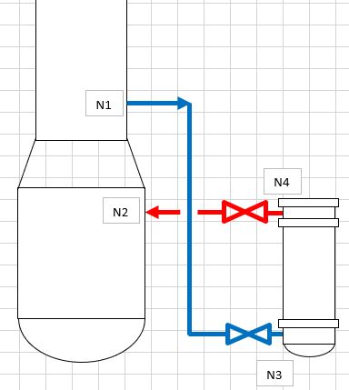
I'm currently looking at a once-through, vertical design (figure attached) for a project I'm working on.


I can provide numbers but I suppose a qualitative discussion should suffice for what I want to ask at this point.


Below is how I understand how the system works:

1. Liquid from column is taken at constant (L1).

2. Nozzle draw off in column (N1) location is higher than the reboiler outlet return nozzle in column (N2).

3. For the sake of discussion, we assume that reboiler outlet nozzle (N3) elevation is same with N2.

4. Flow goes across the reboiler from the bottom, going up.

5. If there's no heat input in the reboiler, the effective flow to the reboiler (L2) will be determined by the available static head (N1-N2) going against the total resistance of the circuit, which would be from the inlet and the outlet piping pressure drop, as well as the pressure drop inside the exchanger (with pure liquid flowing as heat input =0).

6. If L2 > L1, then you will draw more liquid than what's coming from the column, so it follows that the inlet piping to the reboiler will be partially filled with liquid. If L2 < L1, you will have back up of liquid in your column.

7. Exchanger elevation relative to column has little effect in L2.


If heat is applied to the reboiler:

8. You will have pressure drop increase in both reboiler outlet piping and inside the reboiler itself due to two phase flowing

9. However, the static head will change inside the reboiler due to presence of vapor.

10. In this case, point 7 no longer applies and change in exchanger elevation relative to column will have an effect in L2. I think this is the essence of doing the thermosyphon hydraulics, to establish the height required to make L2 = L1


Here are my questions:

1. My intuition tells me that if we follow the schematic above, you will always have driving force to establish flow and it is possible to have more driving force than required by the system to establish L1. If that's the case, shall I expect the reboiler inlet piping to be partially filled with liquid? Since the fluid is saturated, shall I expect flashing within this line?

2. We design the reboiler to provide enough surface area to allow a liquid with flow L1 to boil off to a target vapor fraction, for a given heat duty (and steam flow, by extension). In reality, if the flow to the reboiler is different from design (say L2 > L1), you will produce a different vapor fraction at your reboiler process outlet, and the heat duty may be different from design since your heat transfer coefficient might change due to differences in boiling regime. How do we ensure that we are designing the thermosyphon circuit will actually work as intended?


Attached Thumbnails

  • Schematic.JPG


#2 Pilesar

Pilesar

    Gold Member

  • Members
  • 1,376 posts

Posted 12 October 2022 - 11:16 AM

The inlet to the reboiler will be liquid. The liquid at the reboiler inlet is lower than its bubble point temperature. The liquid was saturated when it left the feed tray. At the reboiler inlet, the liquid is subcooled because it is at a higher pressure due to the liquid head above it. The vapor fraction inside the exchanger and in the outlet piping affects the pressure drop which affects the circulation rate. The system balance of vapor fraction and flow and heat transfer is dependent on the pressure drop in the piping and the exchanger which should be closely considered during the design phase. The heat transfer rate can change significantly depending on the operating conditions. Film boiling is to be avoided if possible. A good heat exchanger simulation program can help with the complicated calcs. Outlet vapor fraction is usually not a controlled variable after installation -- most often the exchanger duty is what is important. A variable pressure drop device (butterfly valve) is sometimes (not usually) installed at the reboiler inlet to bring the inlet liquid closer to saturation. Inlet valves can make up for design uncertainty and adjust the exchanger area required to bring the liquid back to its boiling temperature. Thermosiphon exchangers have a wide range of operation so are usually designed so they will work under all expected conditions. A once-through reboiler can be designed so that all the liquid from the column is trapped and sent to the inlet. Exchanger duty would then be dependent on the hot side conditions.


#3 Bobby Strain

Bobby Strain

    Gold Member

  • Members
  • 3,529 posts

Posted 12 October 2022 - 12:34 PM

Is this system now in the design phase? Or is this simply a curiosity?


Bobby


#4 breizh

breizh

    Gold Member

  • Admin
  • 6,334 posts

Posted 12 October 2022 - 06:28 PM

Hi,

Probably good to study the papers attached.

Good luck

Breizh


#5 Bobby Strain

Bobby Strain

    Gold Member

  • Members
  • 3,529 posts

Posted 12 October 2022 - 11:17 PM

This is not a true thermosyphon but a forced feed reboiler. It is once through and vaporization is set by the heat duty. Thermosyphons can be designed to develop a predetermined vapor fraction at the outlet. This requires re-circulation of some of the outlet liquid. You must have some reason for using the exchanger you describe. Probably a wide boiling range material. Or a solvent absorber system where there is a large temperature difference between the solvent and solute.

Without knowing what the components are, it's impossible to make suggestions about the appropriateness of such a system.


Bobby


#6 shvet1

shvet1

    Gold Member

  • Members
  • 338 posts

Posted 12 October 2022 - 11:18 PM

3. For the sake of discussion, we assume that reboiler outlet nozzle (N4) elevation is same with N2.


2. We design the reboiler to provide enough surface area to allow a liquid with flow L1 to boil off to a target vapor fraction, for a given heat duty (and steam flow, by extension). In reality, if the flow to the reboiler is different from design (say L2 > L1), you will produce a different vapor fraction at your reboiler process outlet, and the heat duty may be different from design since your heat transfer coefficient might change due to differences in boiling regime. How do we ensure that we are designing the thermosyphon circuit will actually work as intended?


As Bobby mentioned there is no enough information to guide you. 


If issue does not concern draw-of design then:

Kister's Distillation Troubleshooting chap. 23 and particularly cases 23.3, 23.5, 23.8

Kister's Distillation Operation chap. 15 and particularly fig. 15.4.a


Anyway relevant chapters in Kister's books (above + Distillation Design) are highly recommended for beginners.

If too wide hydraulic regime of reboiler is foreseen we install a full-bore valve upstream of reboiler to control surge manually. If a start-up problem is foreseen we install a light gas connection downstream of reboiler to control siphon force during warming up.


Edited by shvet1, 12 October 2022 - 11:28 PM.


#7 Dacs

Dacs

    Gold Member

  • Members
  • 393 posts

Posted 13 October 2022 - 02:31 AM

This is not a true thermosyphon but a forced feed reboiler.


Agreed, and I see it this way as well.


Thermosyphons can be designed to develop a predetermined vapor fraction at the outlet. 


This is what I have been exposed to (circulating thermosyphon) and I do fully understand how the design works, and be able to do a design out of it, but going back to my queries...


You must have some reason for using the exchanger you describe. Probably a wide boiling range material. 


This is for regenerating 40 wt% MDEA solution (Amine Regeneration). Existing systems similar to this one at the client facilities have this once through design. Client standard also allows usage of thermosyphon design.


For more info: The current design I'm working on (based on thermal rating and with the reboiler outlet nozzle elevation = column reboiler product inlet nozzle, same as with the sketch I shared) will result in available head for thermosyphon flow (AHTF) > required head for thermosyphon flow (RHTF) (these abbreviations are from client standards by the way). Client standard requires a balancing line from the vapor section of the draw off tray to the reboiler inlet piping if AHTF > RHTF.


To make AHTF = RHTF, I need to elevate the reboiler, which does not make any sense from construction point of view (unnecessarily increase structure/foundation costs, just to kill the head?). So this has triggered all this mental gymnastics in my head making sense of it.


One document breizh provided has given me insight (see attached). It essentially says that changing the head (within optimal range) while results in varying circulation rate, will not vary much the heat flux (essentially heat duty) at the reboiler. So it answers one of my question (ensuring duty will remain the same). So what's left is how to ensure that we maintain the target circulation rate. 


To kill the head, the balancing line will introduce vapor at the reboiler inlet to maintain the flow from the column to the reboiler. It makes sense to me. Or does it?


Attached Thumbnails

  • Heat Flux.JPG


#8 Bobby Strain

Bobby Strain

    Gold Member

  • Members
  • 3,529 posts

Posted 13 October 2022 - 04:17 PM

Design the heat exchanger such that it fits your available head, with some margin. And pay attention to the design of the draw tray and piping. It's a fairly simple hydraulic calculation. HTRI or other design programs should be able to do all this for you. A balancing line is useless; it will only fill with liquid. If you want to have some control, provide a full-open ball valve in the liquid inlet.


Bobby


Edited by Bobby Strain, 13 October 2022 - 04:20 PM.


#9 breizh

breizh

    Gold Member

  • Admin
  • 6,334 posts

Posted 13 October 2022 - 10:42 PM

Hi,

To add to the discussion, one important nozzle equipped with valve is missing on the shell to remove non condensable at the startup of the unit.

Note: make sure the steam quality is stable, not overheated, this will affect the heat transfer very much. Based on experience.

Good luck

Breizh 


#10 Dacs

Dacs

    Gold Member

  • Members
  • 393 posts

Posted 16 October 2022 - 05:33 AM

HTRI or other design programs should be able to do all this for you.


I did for HTRI and also did manual calculation, both agreed that more than enough head is present.


A balancing line is useless; it will only fill with liquid. 


I wish I can make direct quote of our client standard, but it is specifically mentioned that this is needed if available head > required head.


The balancing line in particular is required to be at the vapor space of the drawoff tray, so its intent is to introduce vapor to the reboiler inlet line.


Going back to what I have: Since the current exchanger is oriented vertically (facility is limited in plot space), aligning the reboiler outlet line with the reboiler outlet to column nozzle (see attached sketch in my 1st post), available head > required head. I can remedy this by lifting the reboiler to some extent, but (1) it will be a waste of foundation/structure and (2) the reboiler outlet nozzle will be above the corresponding column nozzle, which I have never seen in my experience.


To add to the discussion, one important nozzle equipped with valve is missing on the shell to remove non condensable at the startup of the unit.


Process is tube side, but worthwhile considering.

Note: make sure the steam quality is stable, not overheated, this will affect the heat transfer very much. Based on experience.

Good luck


I have placed a desuperheater upstream of the steam feed, to ensure steam quality.


Edited by Dacs, 16 October 2022 - 05:34 AM.


#11 Bobby Strain

Bobby Strain

    Gold Member

  • Members
  • 3,529 posts

Posted 16 October 2022 - 12:47 PM

Your client must not have good standards if they insist on this kind of nonsense. Be wary of any advice they provide. I have had clients like this, too.


Bobby


#12 Dacs

Dacs

    Gold Member

  • Members
  • 393 posts

Posted 17 October 2022 - 06:20 AM

Your client must not have good standards if they insist on this kind of nonsense.


Let me put it this way: it is very hard to argue with the biggest oil company in the world.  :P


Reply to this topic


Similar Topics