Jump to content


Featured Articles

Check out the latest featured articles.

File Library

Check out the latest downloads available in the File Library.

New Article

Product Viscosity vs. Shear

Featured File

Vertical Tank Selection

New Blog Entry

Low Flow in Pipes- posted in Ankur's blog

0

Heat Balance For A Steam Reformer Unit


264 replies to this topic
Share this topic:
| More

#201 MurtazaHakim

MurtazaHakim

    Gold Member

  • Members
  • 110 posts

Posted 23 April 2018 - 05:03 AM

All the duties and quantities enlisted in the preceding message (#200) are in good agreement with the values we have calculated so far. However one figure seems to be controversial which is as follows:

 Generating that 56.66 kmol/h HPS from 242 oC BFW (and taking into account 5 % CBD at 257 oC) requires a duty of about 497 kW.

 As far as we remember the BFW after being preheated to 242 degrees Celsius enters the steam drum (which is a part of the black box), which I think is responsible for the 15 degrees Celsius increment thereby taking the BFW to 257 degrees Celsius after which the partial vaporization begins (message #199). If the SD is responsible for that 15 degrees C increment we cannot consider the flue gas to impart 491 kW of duty. In that case we calculated 475 kW of heat duty required for 30-242 degrees Celsius for BFW. This is true only if we consider the SD to be outside the convection section.


The cause of temperature difference obtained in heat integration using ASPEN ENERGY ANALYZER has already been pointed out by you in message #195.


Design is usually for a vaporization of 20 % or so

How do we decide the vaporization percentage ? What are the factors responsible for calculating the vaporization percentage ?


In message #199 you mentioned that the heat exchange in the convection section does not utilize conventional heat exchangers. What type of equipment are employed then for heat exchange in the convection section of the furnace ?


Edited by MurtazaHakim, 23 April 2018 - 05:05 AM.


#202 PingPong

PingPong

    Gold Member

  • Members
  • 1,446 posts

Posted 23 April 2018 - 07:01 AM

The steam drum is adiabatic and does not add any duty.


Duty is only added in the WHB and the convection vaporizing coil.


The heat to bring the all BFW (including CBD) from 242 oC to 257 oC and turn 95% of it (except the 5% CBD) into saturated 257 oC HPS comes completely from the WHB and the convection vaporizing coil. That takes 1070 kW (573 kW in the WHB plus 497 kW in the convection coil).


The 20 % vaporization is just a typical design number. It sets the hot water recirculation flow and thereby the hydraulic design of the WHB, convection vaporizing coil and associated piping. You need not worry about it as it does not affect the heat balance.

It only affects the actual water temperature in the steam drum, as the 242 oC BFW is mixed with four times as much recirculating hot 257 oC water, resulting in a mixture temperature of about 254 oC in the drum. So in case of a design for 20 % vaporization the water flow to the vaporizers will in reality not be above mentioned 128.15 kmol/h at 242 oC but about 640 kmol/h at about 254 oC. Once again: that has no impact on the heat balance as both situations take exactly the same amount of kW to bring the water to 257 oC.


The convection section of a furnace contains horizontal tubes in a rectangular structure. The hottest tubes are bare, other tubes can have studs and others fins. You can use google images to find typicals for furnace convection banks. Designing such a system for a steam reformer furnace is something that I would not even attempt. Your supervisor should not request you to do that as this is work for specialists.


#203 ravindra@096

ravindra@096

    Veteran Member

  • Members
  • 41 posts

Posted 24 April 2018 - 04:58 AM

The fact that the steam drum is adiabatic and does not add any heat duty and that the heat required for the (1) BFW to reach 257 degrees Celsius from 242 degrees Celsius and then (2) to vaporise the 95% of BFW is entirely provided by the WHB and the convection section vaporizing coil has led us to modify the calculations which are as follows:


(1120.1-1047.2) kJ/kg * 18.015 kg/kmol * 59.63997 kmol/hr / 3600 = 21.75688 kW............................ (1)


(1677.75)  kJ/kg * 18.015 kg/kmol * 56.65797 kmol/hr / 3600 = 475.68562 kW ................................... (2)


Total heat required for export HPS generation = 21.75688 + 475.68562 = 497.4425 kW


The circuit involving the flue gas has now successfully converged resulting in the flue gas final temperature of 150 degrees Celsius. However the WGSR effluent stream is divided into two parts one having a target temperature of 152.8 degrees Celsius (dew point of steam) from 420 degrees Celsius and cooling duty of 290.9634 kW and another part having supply and target temperature of 152.8 and 45 degrees Celsius respectively with cooling duty of 481.3395 kW. The DM water preheat (process) stream requires 316.69707 kW for meeting the target of 242 degrees Celsius whereas the exchanging WGSR effluent stream (one) provides only 290.9634 kW only which results in the DM water getting preheated only to 224.8 degrees Celsius instead of 242 degrees Celsius. I think we need to iterate more on the condensation profile in order to have the target temperatures achieved.


In the preceding message #202 you said that it is difficult to design the convection bank tubes and it is the work of specialists. Can you please elaborate on the design parameters and procedure for the convection bank tubes ? Is it not possible to have at least a preliminary design of those tubes ?


What would be our next move in the process ? Do we now go for the design of WHB, WGSR effluent exchanger and other associated hardware like steam drum (Et cetera) ?  


Edited by ravindra@096, 24 April 2018 - 05:01 AM.


#204 PingPong

PingPong

    Gold Member

  • Members
  • 1,446 posts

Posted 24 April 2018 - 07:45 AM

In the preceding message #202 you said that it is difficult to design the convection bank tubes and it is the work of specialists. Can you please elaborate on the design parameters and procedure for the convection bank tubes ? Is it not possible to have at least a preliminary design of those tubes ?
I am not one of those specialists.

Problem is find formulas for manual calculation of the heat transfer and the pressure drop on the flue gas side for tubes with fins, with studs, and bare.

What would be our next move in the process ? Do we now go for the design of WHB, WGSR effluent exchanger and other associated hardware like steam drum (Et cetera) ?
That is not for me to decide. If your supervisor wants you to dimension all equipment then I guess you have to.


Murtaza mentioned to me that there is only one month left to finish all work, including kinetic calculations for reformer and shift catalyst. I can't imagine that you will be able to do kinetics, furnace coils, exchangers, vessels, et cetera in one month as it took four months just for the heat balance.


I suggest you decide together with your supervisor what the work priority is from now on, in which order you are going to do what, and what work can be dropped if time runs out.


#205 MurtazaHakim

MurtazaHakim

    Gold Member

  • Members
  • 110 posts

Posted 25 April 2018 - 05:47 AM

Design of fired heater seems to be an arduous task. However you could at least enlighten us with the type of furnace employed in case of SMR units. Are API 560 standards applicable for the design of fired heaters in SMR units (since it is titled for general refinery services) ?


Our supervisor insists on moving ahead with the kinetics. He believes that it is more important for a Chemical engineer to find the conversion, selectivity and/or the amount of catalyst required for achieving that conversion and selectivity. After the kinetic calculations we are expected to perform calculations involving the equipment sizing followed by simulation of the entire plant in a process simulator. The equipment sizing activity should also include sizing of hydrogenator vessel (amount of catalyst) and zinc oxide bed in the pre-treatment section of the plant. We are asked to assume the amount of sulphur present in the feed and proceed for the calculations of pre-treatment section equipments.


#206 PingPong

PingPong

    Gold Member

  • Members
  • 1,446 posts

Posted 25 April 2018 - 08:21 AM

Steam reformer furnaces are very difficult to design because of the extreme temperatures, much higher than in refinery furnaces. Part of API 560 will be applicable but there will be more to it.


Only a few licensors (CB&I, Foster Wheeler, Haldor Topsoe, Technip, ......) design such furnaces, so probably there are no more than a hundred or so specialists in the world doing that work. I am not one of them, and you should not try to be.


Each licensor has its own specific furnace design for big units. CB&I and Technip use top firing (burners in the roof of the radiant cell firing downward), Haldor Topsoe uses sidewall burners, Foster Wheeler use their proprietary Terrace Wall firing. In all these designs the radiant cell is a high and long rectangular box and the process gas flows downwards through vertical catalyst filled tubes.


Your SMR however has a very small capacity and therefor would not use any of the above designs but a vertical cylindrical furnace with the process gas flowing upwards through catalyst filled tubes located along the wall and bottom burner(s) in the middle, or the tubes in the form of a cross and burners around them. View from the top:


Attached File  Small Cylindrical Steam Reformer Furnace, top view.jpg   106.89KB   3 downloads


Haldor Topsoe uses a very different design for small capacities, called a Convection Reformer (HTCR), but that would have a different heat balance than our calculations sofar, so you can forget that..


#207 MurtazaHakim

MurtazaHakim

    Gold Member

  • Members
  • 110 posts

Posted 26 April 2018 - 11:12 AM

Now we must begin with the kinetic calculations. How do we proceed further in the kinetic calculations ? What parameters are to be evaluated in the kinetic calculations ?

Edited by MurtazaHakim, 26 April 2018 - 11:14 AM.


#208 PingPong

PingPong

    Gold Member

  • Members
  • 1,446 posts

Posted 26 April 2018 - 12:34 PM

I can't help you with that as I have no kinetic data for Reformer or HTS.


Normally a catalyst vendor is contacted to provide a quote for the amount of catalyst required based on the specifications (inlet flow and composition, inlet T and p, outlet T and p, outlet composition) provided by the process designer (like me). As a process designer I only need to know the typical ATE. That may be surprising for your supervisor, but that is reality.


You will have to google a lot to try to find something usable.


#209 MurtazaHakim

MurtazaHakim

    Gold Member

  • Members
  • 110 posts

Posted 27 April 2018 - 02:01 PM

The kinetic data is confidential data for the companies. Convincing someone working for the catalyst manufacturing company to deliver the kinetic data seems a difficult task. We have obtained a research paper which is attached herewith. Could it be of any use in determining the type and amount of catalyst required to achieve the ATE ?


Is it not possible for process designers to have access to kinetic data ? Is there not any process in which the process designers working for the EPC companies verify the quote from the catalyst vendor(s) ? 


We would appreciate any help from the members of this esteemed forum who have worked for the catalyst vendors and could provide any details on the kinetic data of a conventional SMR unit having high temperature shift reactor along with the main reformer.


Attached Files


#210 PingPong

PingPong

    Gold Member

  • Members
  • 1,446 posts

Posted 28 April 2018 - 05:22 AM

Convincing someone working for the catalyst manufacturing company to deliver the kinetic data seems a difficult task.
No, you can forget that. At best they may refer you to an article in a scientific magazine.

We have obtained a research paper which is attached herewith. Could it be of any use in determining the type and amount of catalyst required to achieve the ATE ?
Note that it states: "..... in an
adiabatic packed bed reactor", ".... in the temperature range of 300 - 700 oC at 1 bar. ", ".... under the conditions of
diffusion limitations and away from the equilibrium conditions."

An SMR is not adiabatic and works much hotter. I suspect that the investigators did not have an industrial SMR in mind, but were only interested in reforming for production of low pressure hydrogen for fuel cells.

You will need to google more.

Is it not possible for process designers to have access to kinetic data ? Is there not any process in which the process designers working for the EPC companies verify the quote from the catalyst vendor(s) ?
Only process engineers working for a reputable licensor and cooperating with a specific catalyst vendor for their licensed process may have some means of calculating the required catalyst volume. Process engineers working for EPC companies not.


There are many catalyst vendors and each has multiple catalysts for each application, each with their own composition, activity, pros & cons. It would be impractible to try to manage them all. Based on previous projects each EPC company will have data that may allow a process design engineer to make a rough estimate of required catalyst. 


The catalyst vendor(s) will guarantee the performance and runlength of the catalyst.

It is not really different from when for another equipment for example a compressor vendor responds with a quote. I don't check whether the proposed compressor has enough wheels of the right diameter and the right shape of vanes. I could not, even if I wanted. The guarantee of a reputable vendor is enough. If it would not work later then that vendor would have a problem.


#211 PingPong

PingPong

    Gold Member

  • Members
  • 1,446 posts

Posted 28 April 2018 - 02:44 PM

A few documents that may be of use to you:


#212 MurtazaHakim

MurtazaHakim

    Gold Member

  • Members
  • 110 posts

Posted 30 April 2018 - 04:54 AM

The investigation of Xu and Froment has temperature and pressure limitations. The conditions employed by them are far from what is observed in the industrial practice. The above documents are quite helpful in understanding the kinetics but I guess we will have to make an assumption, choose a correlation and go ahead. For SMR reactions, we have two correlations to choose from, the images of which are attached herewith. In case of WGSR too we have a few correlations to choose from but the issue is none of them have the pressure range which is encountered industrially. What are your suggestions regarding the kinetics correlations ?

Attached Files


#213 PingPong

PingPong

    Gold Member

  • Members
  • 1,446 posts

Posted 30 April 2018 - 08:39 AM

If I were you, I would first model the WGS reactor as that is simpler than the Reformer, and moreover operates adiabatic. In the mean time you can part time google further for additional Reformer kinetic data.,


If I were you, I would first compare all the different available correlations for HTS kinetics by calculating r both at the inlet and outlet conditions of the WGS reactor.


The Boon correlation that you selected contains a PH2S-0.3 term, which is a problem because in your unit PH2S is zero, so the calculated r would automatically be infinite.


I have another article that may be of interest:


Attached File  Validation of a water–gas shift reactor model based on a commercial FeCr catalyst - van Dijk et al 2014.pdf   1.44MB   30 downloads


The HTS feed in that pilot plant contained 5 - 20 ppm H2S but it was found that such low concentrations had no impact on r. See the text and their Figure 3. So their formulas (19) through (22) in combination with the coefficients from Table 2 should be usable for your WGSR. The HTS catalyst in that pilot plant was Haldor Topsoe SK-201-2.
https://www.topsoe.c...alysts/sk-201-2


Edited by PingPong, 30 April 2018 - 09:27 AM.


#214 MurtazaHakim

MurtazaHakim

    Gold Member

  • Members
  • 110 posts

Posted 01 May 2018 - 01:39 PM

The formulae 19 through 22 in the article attached in the preceding message are used to calculate the value of at the inlet and outlet temperatures of WGSR. The expression number (20) for calculation of kT at temperature T however is calculated as zero. The value of (-Ea/RT) at 626.15 K is calculated as -2110.988083 the exponential of which is coming out to be zero. The partial pressures at the inlet raised to their respective reaction orders are calculated successfully along with the (1-β) term. The ln (k0term is used to calculate kwhich is calculated as 8975417.416 for ln(ko) = 15.3 + 0.71. There are two calculated values for some variables as they have a +- b form which gives upper limit and lower limit of that variable for example Ea has values 106 +- 3.9 kJ/mol. r cannot be zero since it is the amount of CO reacted per amount of catalyst per unit time. We are stuck in resolving this issue.The thumbnails are attached herewith.

Attached Files


#215 PingPong

PingPong

    Gold Member

  • Members
  • 1,446 posts

Posted 02 May 2018 - 03:32 AM

The value of (-Ea/RT) at 626.15 K is calculated as -2110.988083
I suggest you calculate that again.

There are two calculated values for some variables as they have a +- b form which gives upper limit and lower limit of that variable for example Ea has values 106 +- 3.9 kJ/mol.
Ignore those upper and lower limits, use a, not a +/- b.

#216 MurtazaHakim

MurtazaHakim

    Gold Member

  • Members
  • 110 posts

Posted 02 May 2018 - 09:01 AM

The necessary corrections have been done. The exponential term had to be calculated upto 10 decimal places due to which it was difficult to continue for the rest of the calculations. R is taken as 8.314 J/mol.K in order to render the exponential term dimensionless. K0 and KT have the same dimensional unit and for them to have same dimensions the exponential term must be dimensionless. The r value for the inlet temperature of 353 °C is calculated as 0.010228107 mol/kg.s which is equal to 0.036821185 kmol/kg.hr which implies that 1 kg of catalyst would convert 0.036821185 kmol/hr of CO into product(s). The amount of CO converted is COinlet – COoutlet = 10.27912 – 3.23619 = 7.04293 kmol/hr. Hence the amount of catalyst required for converting that 7.04293 kmol/hr of CO is 7.04293/0.036821185 = 191.273855 kg. Similarly at outlet temperature r = 0.002606174 mol/kg.s = 0.0093822264 kmol/kg.hr. The amount of catalyst is then calculated as 7.04293/0.0093822264 = 750.6672 kg.


Are the calculated numbers reasonable ? Are the calculations correct now ? The thumbnails are attached herewith.


Which temperature (inlet or outlet) should we calculate r at, since the temperature increases along the length of the reactor ?


You mentioned that the WGSR is adiabatic and hence easy to model. How is an adiabatic reactor easy to model than the one which is not (like reformer) ?


You also mentioned that the catalyst ages and the space velocity is so chosen that the guaranteed catalyst cycle length is achieved. How do we determine the space velocity so that the said objective is achieved ?

Attached Files


#217 PingPong

PingPong

    Gold Member

  • Members
  • 1,446 posts

Posted 02 May 2018 - 01:43 PM

I will later try to understand what you calculated, when I have more time.


Which temperature (inlet or outlet) should we calculate r at, since the temperature increases along the length of the reactor ?

Neither.

What I said was: compare all the different available correlations for HTS kinetics by calculating r both at the inlet and outlet conditions of the WGS reactor.

I assume that in your final report you will have to justify the correlation that you will use to calculate the WGS catalyst volume.

Your supervisor may already earlier question why you choose a particular correlation and not one of the others.

But if you feel that that will not be an issue then you can choose whatever correlation you like.


Anyway, after a correlation is selected (van Dijk 2014, or Boon 2009, or whichever) you need to split the reactor into say 20 horizontal slices, each converting say 5 % of the total CO converted.

Calculate the gas composition at the outlet of each slice,

and then calculate the T at the oulet of each slice (similar calculation as you did months ago to determine the WGSR inlet T).

Calculate r at all calculated intermediate T's.

Use average r of each slice to determine required amount of catalyst in each slice.

Sum of all 20 slices then gives total amount of catalyst.


Edited by PingPong, 02 May 2018 - 01:46 PM.


#218 ravindra@096

ravindra@096

    Veteran Member

  • Members
  • 41 posts

Posted 03 May 2018 - 10:56 AM

The WGS reactor is divided into 20 slices and the gas composition at the end of each slice is stoichiometrically calculated as follows: 

Total CO converted = COinlet – COoutlet = 10.27912 – 3.23619 = 7.04293 kmol/hr

Only one reaction CO+ H2O ===> CO2 + H takes place throughout the reactor. 1 mole of CO and 1 mole of H2O is consumed to produce 1 mole each of CO2 and H2. For example, at the end of slice 1, the amount of CO = CO at 353 °C - (7.04293*0.05), similarly the amount of H2O = H2O at 353 °C - (7.04293*0.05), the amount of CO2 = CO2 at 353 °C + (7.04293*0.05) and the amount of H2 = H2 at 353 °C + (7.04293*0.05). In the same way at the end of each slice the amount of CO and H2O reduces in a way that their amount in the preceding slice is subtracted by (7.04293*0.05) for the next slice and for CO2 and H2 the amount increases after each slice in such a way that the succeeding slice has CO2 = CO2 in preceding slice + (7.04293*0.05) for each slice. Similarly the amount of H2 is calculated for each slice in the same manner as that of CO2. We have attached the thumbnail of slices for verification,please have a look.The outlet of one slice is the inlet of the succeeding slice.


We have also calculated the temperature at the outlet of each slice by the method suggested by you. The value of r is then calculated at the corresponding temperatures. The r initially increases upto 390 °C and then decreases drastically. What could be the reason for that nature of r ? The thumbnails of rest of the calculations are attached herewith. 


If the above done work is correct then please explain how to take average of r for each slice and then determine the catalyst amount required for each slice and then ultimately the addition of 20 such amounts would give us the total amount of catalyst required for the WGS reactor. 

Attached Files


#219 PingPong

PingPong

    Gold Member

  • Members
  • 1,446 posts

Posted 03 May 2018 - 11:14 AM

Your thumbnails in #216 are correct.

The exponential term had to be calculated upto 10 decimal places due to which it was difficult to continue for the rest of the calculations.

Note that kT = exp(ln(ko) - Ea/R.T)


Note also that ln(ko) is given as 15.3 +/- 0.71, so its decimal is not really significant. Therefor Ea/R.T need only be calculated with one decimal.


You also mentioned that the catalyst ages and the space velocity is so chosen that the guaranteed catalyst cycle length is achieved. How do we determine the space velocity so that the said objective is achieved ?
Required amount of catalyst is much bigger than calculated with such academic correlation for two reasons:

(1) the catalyst has an effectiveness factor much smaller than 1.0 due to limitations in pore diffusion (remember Thiele modulus from one of your textbooks)

(2) the catalyst degrades over time, so a lot of extra catalyst is required for a typical runlength of 5 years.


As a result of (1) and (2) required catalyst quantity can be a factor 3 to 5 than calculated with van Dijk 2014 correlation.


#220 PingPong

PingPong

    Gold Member

  • Members
  • 1,446 posts

Posted 07 May 2018 - 12:17 PM

I did not notice your message #218 until now. Apparently it was posted while I was typing my message #219.


Your calculations in #218 look OK to me.


r decreases after some point because CO decreases, and moreover as equilibrium is approached the reverse reaction rate increases which results in decrease of (1-β).


Average r of each slice is simply what it says.

For example: slice 1 has r = 0.010228 mol/s.kg at its inlet and r = 0.010785 at its outlet,

so slice1 has an average r  = ......... mol/s.kg = ......... kmol/h.kg

Theoretical kg of catalyst required for slice 1 is amount of CO converted (kmol/h) in slice 1 divided by its average r (kmol/h.kg).


#221 MurtazaHakim

MurtazaHakim

    Gold Member

  • Members
  • 110 posts

Posted 07 May 2018 - 02:55 PM

The amount of the catalyst required for WGS reactor is calculated as 180.1897 kg. The actual requirement should then be a factor 3 greater than the one calculated using the academic correlation due to factors (1) and (2) mentioned in the message #219. We need to know the density of the catalyst in order to determine its (catalyst) volume and consequently the number of tubes for filling the entire amount of catalyst. The number of tubes would be calculated as the total catalyst volume divided by the volume of one tube. The tube is cylindrical in shape and hence its volume can easily be calculated. The attached thumbnail awaits your verification. I think it is not so important for a process engineer to carry out mechanical design of the reactor, is it ? 


Next comes modeling of the reformer. How do we proceed further for modeling the reformer to calculate the amount of catalyst required to achieve the ATE in the reformer ?

Attached Files


#222 PingPong

PingPong

    Gold Member

  • Members
  • 1,446 posts

Posted 07 May 2018 - 04:16 PM

I calculated 181 kg catalyst so I trust your calculation is correct (without checking it in detail).


The actual amount of FeCr catalyst that is used in an HTS reactor in an SMR designed for hydrogen production is normally roughly 0.5 liter (0.6 kg) per Nm3/h of H2 product.


Your SMR produces about 1100 Nm3/h of H2 so your HTS reactor should contain about 0.55 m3 (660 kg) of FeCr catalyst, almost 4 times the theoretical amount.


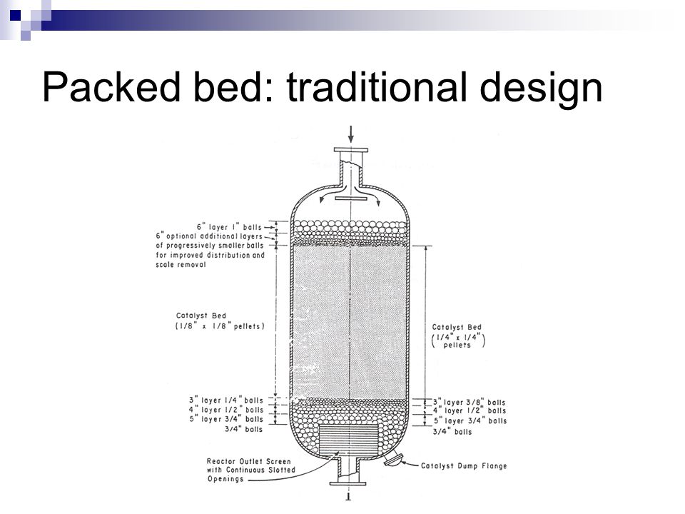
There are no catalyst filled tubes in the HTS reactor.

It will look roughly like this example of just another (not HTS) packed bed reactor:


Packed+bed%3A+traditional+design.jpg


The H/D ratio of the catalyst bed shall be at least 1.


Above and below the catalyst there are layers of ceramic balls.


#223 MurtazaHakim

MurtazaHakim

    Gold Member

  • Members
  • 110 posts

Posted 08 May 2018 - 05:25 AM

The WHSV parameter for WGS reactor is calculated as follows:

WHSV = Weight of the feed charged into the reactor / weight of the catalyst charged into the reactor

WHSV = 1464.11924 kg hr-1 / 660 kg = 2.21836 hr-1


What about the weighted average bed temperature of the WGS reactor ? 


In the preceding message you mentioned the density of the catalyst as 0.55 m3 for 660 kg which is equal to 1200 kg m-3. Is it the particle density ? The bulk density however is in the range of 7000 kg m-3 (mentioned in research article  A review of WGS reaction kinetics in message #211). Moreover you mentioned that the WGS reactor will roughly look like the packed bed reactor. What differences do we encounter between a conventional fixed bed reactor and an HTS reactor. Is it an upflow reactor I mean where is the feed entrance ? 


A cylinder with radius of 0.4 m and height of 1.1 m provides volume of 0.55 m3 such that the criterion of H/D ≥ 1 is satisfied (H/D = 1.375).  How much height should be taken for both upper and lower side for supports (ceramic balls) ? Are the design calculations realistic ? What are the other parameters expected to be known while reactor design is carried out ?


#224 PingPong

PingPong

    Gold Member

  • Members
  • 1,446 posts

Posted 08 May 2018 - 06:50 AM

Bulk density of FeCr catalyst varies for vendors and cat types.

I used here a typical bulk density of 1200 kg/m3 but actual value depends on h/d ratio of cat particles, as that sets void fraction of the bed, and the exact composition and pore volume of the cat, as that sets the particle density. Don't worry about it.


I don't see that 7000 kg m-3 in the mentioned article, but in any case that number would be completely wrong.


Each licensor will use a slightly different design for the internals of the reactor, layers of ceramic balls, support grid or ceremic balls at bottom, et cetera. You should not loose any sleep over that, that typical drawing is good enough for your reactor. It shows on the right side the typical layers of ceramic balls for cat particles of 1/4 inch, which happens to be about the typical cat size that vendors use for HTS. Reactor inlet is at top as indicated. Assume top of upper layer of ceramic balls is at top tangent line or slightly lower. Assume that bottom of catalyst bed is say 100 mm above btm tangent line. 800 mm ID and 1100 mm cat height are OK. Don't loose yourself in more detail.


WABT:


You calculated for each slice the weight of cat, as well as the total cat weight, so for each slice i you can calculate its weight fraction Wi


You calculated for each slice the inlet and outlet temperature, so for each slice i you can calculate its

WABTi = (Tini + 2*Touti)/3


WABT of total reactor is then the sum of all Wi times WABTi


Edited by PingPong, 08 May 2018 - 06:51 AM.


#225 MurtazaHakim

MurtazaHakim

    Gold Member

  • Members
  • 110 posts

Posted 08 May 2018 - 02:31 PM

The WABT is calculated as 391.6 ⁰C. We need to justify the formula used for the calculation of WABT. How is the formula for WABT calculation derived ? Secondly, in the message #222 you mentioned that an SMR plant for hydrogen production uses 0.6 kg of catalyst per Nm3/hr of hydrogen produced in the HTS reactor. Is this a thumb rule ? We will have to justify this number (0.6 kg cat. / Nm3h-1 H2) to the examiner(s).


The WGS reactor inlet pressure is 20 bar. There should be some pressure drop across the catalyst bed; however our heat and mass balance is based upon the assumption of zero pressure drop across the WGSR. Is it possible to have a catalyst bed offering zero pressure drop ? The thumbnail depicting WABT calculation is attached herewith.


Attached Files

  • Attached File  WABT.PNG   24.69KB   1 downloads


Similar Topics