 FB
FBChemical and Process Engineering Resources


As an engineer, specifying heat exchangers for procurement is an important step in the successful execution of any heat transfer or energy conservation project. Early recognition that there are many different heat transfer technologies available can help in receiving optimized bids for each type of equipment available to you. Through process investigation, the specifying engineer can collect the necessary data to allow the heat exchanger designer to optimize both the mechanical and thermodynamic design of the heat exchanger. Through the specification process, you can uncover critical variables such solids loading, heat transfer duty requirements, available footprint space, maintenance considerations, and others.
Heat Transfer Resources
Although most engineers who are asked to specify a heat exchanger may have the appropriate background in heat transfer knowledge, there are cases when the engineer could benefit from a refresher on the basics of heat transfer and the equipment types involved. Here are some resources that will help you review the basics of industrial heat transfer:
Industrial Heat Transfer Basics:
http://www.cheresources.com/heat_transfer_basics.shtml
Design Considerations for Shell and Tube Exchangers
http://www.cheresources.com/designexzz.shtml
Overall Heat Transfer Coefficients in Heat Exchangers
http://www.cheresources.com/uexchangers.shtml
Correlations for Convective Heat Transfer
http://www.cheresources.com/convection.shtml
Shell and Tube Heat Exchanger Design Manual
http://www.wlv.com/products/databook/databook.pdf
Recognizing and Evaluating the Duty Requirements
The first step in specifying any heat exchanger is to properly evaluate and identify the necessary heat transfer duty requirements. In other words, "what do you need the exchanger to do once it's installed?"Â
A useful tool in evaluating heat transfer duty requirements is the T-Q diagram. This visual tool can help the specifying engineer easily determine what is possible in a given heat exchanger. Let's begin with a simple example.
Due to a process change, one of the plant's main products is exiting the process unit 30 °F higher than before. Sending the product to the storage tank at this elevated temperature may cause safety concerns. As the plant engineer, you've been tasked with specifying a product cooler for this new requirement. The total product stream flow rate is 500,000 lb/h
Previously, the product stream was sent to storage at approximately 130 °F. Now, it's exiting the processing unit at 160 °F. The new product cooler must be able to cool the product stream back down to 130 °F for safe operation. The product stream has physical properties that are very close to those of phenol. For the initial heat balance examination, we'll check the heat capacity of phenol at the midpoint of the cooling duty which is 145 °F to get an average heat capacity through the exchanger. At 145 °F, the heat capacity of phenol is reported as 0.529 Btu/lb °F. Using the following equations:
| Eq. (1) |
| Eq. (2) |
Where:
Q = heat transferred in thermal unit per time (Btu/h or kW)
M = mass flow rate
T = temperature
Cp = heat capacity or specific heat of fluid
Subscript "H"Â = hot fluid
Subscript "C"Â = cold fluid
Solving Equation 1, we find that the heat transfer duty is:
QH = (500,000 lb/h) x (0.529 Btu/lb °F) x (160 - 130 °F) = 7,935,000 Btu/h
Now, we make the following assumption:
- The heat capacity of the cooling tower water is 1.0 Btu/lb °F
- Cooling tower water is available at 88 °F during the warmest summer month
- QH = QC (perfect heat transfer, a typical assumption)
- The tower water can undergo a 20 °F temperature rise in the exchanger
Then, we solve Equation 2 for mC.
mC = (7,935,000 Btu/h) / (1.0 Btu/lb °F x 20 °F) = 396,750 lb/h
This is converted to gallon per minute as follows:
(396,740 lb/h) / (8.27 lb/gal) / (60 min/h) = 800 GPM (nearly a factor of 500, actually 496)
Now, we can construct our T-Q diagram for our system:
 |
| Figure 1: T-Q Diagram for the First Example |
Now, we have the basis for what our heat exchanger needs to perform and we've begun to identify the utility requirements for the duty. At this time, we need to note of couple of items. Firstly, as defined, our heat exchanger may require as much as 800 GPM of cooling tower water to perform the cooling task. An investigation should be made to determine if 800 GPM of cooling tower water is actually available. If not, the duty must be re-examined. In this situation, the engineer finds that he has up to 1000 GPM of water available, so this will not be a concern.
Secondly, we note that our duty does not contain any thermodynamic violations and it does not contain a temperature cross. There are two cases are illustrated below in Figure 2:
 |  | |
| Figure 2: T-Q Diagram Showing a Violation | Figure 3: T-Q Diagram Showing a Temperature Cross |
Notice the T-Q diagram that shows a thermodynamic violation. The cold side is being heated to a temperature that is above the inlet temperature of the hot side. Suppose that in our example, the engineer found that there were only 100 GPM of water available. His analysis would have shown the water would have exited the exchanger far above the 160 °F hot side inlet temperature. In short, this is not enough water to accomplish the duty. At that point, he would have to investigate other utility options.
In the second image above, the T-Q diagram shows what is know as a temperature cross. The cold side outlet temperature is higher than the hot side outlet temperature. It's important to note whether or not your duty contains a temperature cross as it will have a significant impact on the type and number of heat exchangers that may be required to perform the duty.
As the engineer is examining a new heat transfer duty, the concept of NTU or Number of Transfer Units should be used to help guide the specification. A good rule of thumb is that a single shell and tube heat exchanger should be designed with a minimum temperature approach of 10 °F. The "temperature approach" is defined as the temperature difference between the hot side outlet temperature and the cold side outlet temperature. In our example above, the approach temperature is 130 °F-108°F = 22 °F. This duty can easily be accomplished in a single shell and tube heat exchanger.
Now, consider the following duty shown in "Duty 2"Â above. This unit has a deep "temperature cross"Â. This is where the concept of NTU can be helpful. For Duty 2 above (Figure 3), we calculate the NTU for the hot side and the cold side as follows:
 | Eq. (3) |
 | Eq. (4) |
 | Eq. (5) |
LMTD = 39.15 °F
NTUHOT = 150 / 39.15 = 3.83
NTUCOLD = 170 / 39.15 = 4.34
 |
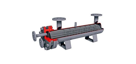
| Figure 4: Shell and Tube Heat Exchanger Flow Pattern |
The NTU can be translated into the approximate number of shell and tube heat exchangers in series that will be required to perform a given duty. The engineer must realize that if it is necessary to perform Duty 2 just as it is shown, it will be an expensive proposition in terms of purchased equipment costs, installation costs, and maintenance costs over the life of the shell and tube heat exchangers.
Shell and tube heat exchanger do a relatively poor job of "temperature crossing"Â due to their lack of purely countercurrent flow as shown in Figure 4.
The shell side of the exchanger is almost always baffled so that a reasonable heat transfer coefficient can be obtained. The tube side flow in this image shows a single tube pass. While this is possible, it's not very common. The tube side velocity is the key to the tube side heat transfer coefficient and the ability to mitigate fouling. For these reasons, multiple tube passes are typically used in shell and tube exchangers. The result of these flow patterns is a lack of countercurrent flow. In fact, the LMTD or Log Mean Temperature Difference in shell and tube heat exchangers has be corrected for these flow patterns. Typically, the calculated LMTD has to be multiplied by a factor of 0.70 to 0.90 to account for the flow patterns.
If Duty 2 is required, the engineer may want to consider a heat exchanger type with truly countercurrent flow such as a pipe-in-pipe (commonly called a hairpin exchanger) or a plate heat exchanger. These devices, with their truly countercurrent flow patterns, can perform duties with temperature crosses in a single unit rather than requiring multiple units in series.
Regardless of the heat exchanger type chosen, the engineer must be aware of this scenario during the initial specification stage for the heat exchanger.
At this point, the engineer has established the basic parameters for the heat exchanger and now other factors need to be investigated prior to the specification process.
1 Comments
what happens if temperature cross occurs in heat exchanger?