Jump to content


Featured Articles

Check out the latest featured articles.

File Library

Check out the latest downloads available in the File Library.

New Article

Product Viscosity vs. Shear

Featured File

Vertical Tank Selection

New Blog Entry

Low Flow in Pipes- posted in Ankur's blog

- - - - -

Caloric Temperature Factor Correction In Heat Exchangers?


This topic has been archived. This means that you cannot reply to this topic.
9 replies to this topic
Share this topic:
| More

#1 Celopsin.Khan

Celopsin.Khan

    Veteran Member

  • Members
  • 33 posts

Posted 09 May 2014 - 02:56 PM

Thermo-physical properties, which are used in Design problems of many equipment are a function of Temperature. 


Now there is this one fact (I m not confirm about it) that while designing a Heat Exchanger if delta T is greater than 50 degrees then we cannot use arithmetic mean Temp of In and Out Temp and we have to use Caloric Temperature Correction. 


1. Now What exactly is Caloric Temperature? and how can we apply this correction.

2. Also if there is linear relation of any property say Cp with temperature at constant API gravity, can we use simple average T for extracting thermo-physical properties for delta T > 50 ?

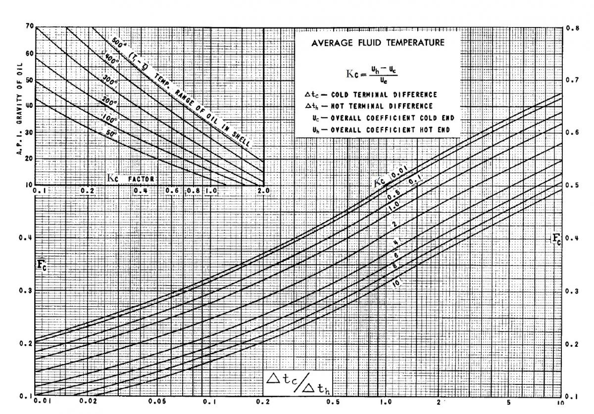
3. Can anyone provide me a clear scanned Figure of "Page 827 | Fig 17 - Caloric Temperature Correction | D. Q. Kern' Process Heat Transfer"


#2 PingPong

PingPong

    Gold Member

  • Members
  • 1,446 posts

Posted 10 May 2014 - 08:28 AM

Caloric Temperature is supposed to be the "correct" average temperature between inlet and outlet of a stream.


When using the stream properties at that temperature one should, in theory, obtain those film coefficients (hi and ho) for tube and shell sides that would result in the correct U value of the exchanger.


Attached Thumbnails

  • Caloric Temperature Correction Factor Fc.jpg


#3 Celopsin.Khan

Celopsin.Khan

    Veteran Member

  • Members
  • 33 posts

Posted 17 May 2014 - 07:59 AM

What range of assumed Overall Heat Transfer Co-efficient should be taken while designing a Crude / Kero Heat Exchanger ... Qern Page 840 states ranges for all types of fluids ... just dont know what range should I take.


Can you have a look at this Design. Assumed U = 260 W/m2 K, Although Linear Velocity is in Range 1 - 5 m/s and Pressure Drop is < 10 psi. But I have little experience designing Heat Exchanger.


Also the Thermo physical Properties have been calculated using Magdi Assaad' Computerized Heat Exchanger Design Procedure. calculation is in done in sheets using Interpolation.
 

Also is there any way (tables or equation) to calculate friction factor (shell and tube sides) without using graphs. ... would be a real peace.?


Is the Design O.K

Attached Files


Edited by Celopsin.Khan, 17 May 2014 - 08:11 AM.


#4 breizh

breizh

    Gold Member

  • Admin
  • 6,333 posts

Posted 17 May 2014 - 08:20 AM

Hi,


for friction factor , use the search engine in this forum :

key words : friction factor and you will find correlations .


Breizh


#5 Celopsin.Khan

Celopsin.Khan

    Veteran Member

  • Members
  • 33 posts

Posted 17 May 2014 - 08:32 AM

Hi,


for friction factor , use the search engine in this forum :

key words : friction factor and you will find correlations .


Breizh


Thanks got it


#6 PingPong

PingPong

    Gold Member

  • Members
  • 1,446 posts

Posted 17 May 2014 - 10:32 AM

Also is there any way (tables or equation) to calculate friction factor (shell and tube sides) without using graphs.
It is very simple to turn every graph into a formula by using curve fitting software. You can find several freeware curve fitting programs on the internet, just google.

#7 srfish

srfish

    Gold Member

  • ChE Plus Subscriber
  • 408 posts

Posted 17 May 2014 - 06:11 PM

It appears that the shell is under-tubed. This could go in a size smaller. The 4 tube passes will probably give a tube side pressure drop higher than 10 Psi.


#8 frnz

frnz

    Brand New Member

  • Members
  • 3 posts

Posted 02 January 2015 - 03:23 AM

Hi .


Can any body help to find the K value for below mentioned conditions of fluid.

1) Kerosene heated from 75F to 120F for P.D of 10PSI.

1) GAsoline Cooled from 160F to 120F for P.D of 07PSI.


I have gone trough the graph shown in Kern Process heat transfer and i got k as .65,is correct or not?


pradeep


#9 srfish

srfish

    Gold Member

  • ChE Plus Subscriber
  • 408 posts

Posted 02 January 2015 - 11:05 AM

Those temperature ranges are too small to be using caloric temperature for physical properties. Fifty degrees is the lowest line shown.on the graph.


#10 frnz

frnz

    Brand New Member

  • Members
  • 3 posts

Posted 18 February 2015 - 09:04 AM

Than , what to do with such cases?

Is their any other way to go or not?


Similar Topics